*7 PLC word addresses defined for integer, float, and string variables must be even-numbered. i.e., IW5 is not a valid device address for an integer variable. Must be either IW4 or IW6.
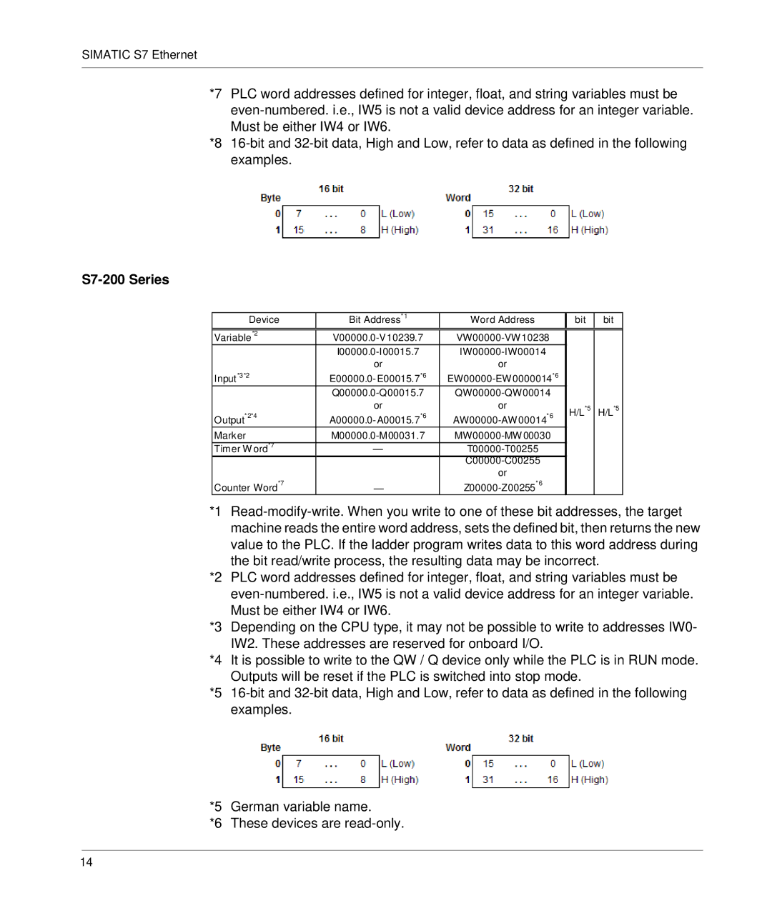
*8 16-bit and 32-bit data, High and Low, refer to data as defined in the following examples.
S7-200 Series
Device | Bit Address* 1 | | Word Address | | bit | bit |
| | | | |
Variable*2 | V00000.0-V10239.7 | VW00000-VW10238 | | |
| I00000.0-I00015.7 | | IW00000-IW00014 | | | |
| or | | or | | | |
Input*3*2 | E00000.0-E00015.7*6 | EW00000-EW0000014*6 | | |
| Q00000.0-Q00015.7 | QW00000-QW00014 | | |
* 2*4 | or | *6 | or | *6 | H/L*5 | H/L*5 |
Output | A00000.0-A00015.7 | | AW00000-AW00014 | | |
Marker | M00000.0-M00031.7 | MW00000-MW00030 | | |
Timer Word*7 | — | | T00000-T00255 | | | |
| | | C00000-C00255 | | | |
| | | or | | | |
Counter Word*7 | — | | Z00000-Z00255*6 | | | |
*1 Read-modify-write. When you write to one of these bit addresses, the target machine reads the entire word address, sets the defined bit, then returns the new value to the PLC. If the ladder program writes data to this word address during the bit read/write process, the resulting data may be incorrect.
*2 PLC word addresses defined for integer, float, and string variables must be even-numbered. i.e., IW5 is not a valid device address for an integer variable. Must be either IW4 or IW6.
*3 Depending on the CPU type, it may not be possible to write to addresses IW0- IW2. These addresses are reserved for onboard I/O.
*4 It is possible to write to the QW / Q device only while the PLC is in RUN mode. Outputs will be reset if the PLC is switched into stop mode.
*5 16-bit and 32-bit data, High and Low, refer to data as defined in the following examples.
*5 German variable name.
*6 These devices are read-only.