SIMATIC S7 Ethernet
System Structure
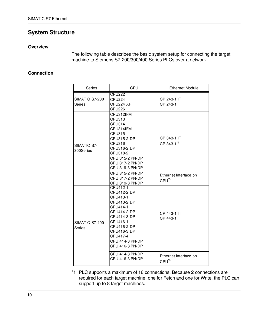
Overview
The following table describes the basic system setup for connecting the target machine to Siemens
Connection
Series | CPU | Ethernet Module | |
|
|
| |
|
|
| |
SIMATIC | CPU222 | CP | |
CPU224 | |||
Series | CPU224 XP | CP | |
| CPU226 |
| |
| CPU312IFM |
| |
| CPU313 |
| |
| CPU314 |
| |
| CPU314IFM |
| |
| CPU315 | CP | |
| |||
SIMATIC S7- | CPU316 | CP | |
| |||
300Series |
| ||
| |||
|
| ||
| CPU |
| |
| CPU |
| |
| CPU |
| |
| CPU | Ethernet Interface on | |
| CPU | ||
| CPU*3 | ||
| CPU |
| |
|
| ||
|
| ||
|
| ||
|
| ||
|
| ||
| CP | ||
| |||
| CP | ||
SIMATIC | |||
| |||
Series |
| ||
|
| ||
|
| ||
| CPU |
| |
| CPU |
| |
|
|
| |
| CPU | Ethernet Interface on | |
| CPU | ||
| CPU*3 |
*1 PLC supports a maximum of 16 connections. Because 2 connections are required for each target machine, one for Fetch and one for Write, the PLC can support up to 8 target machines.
10