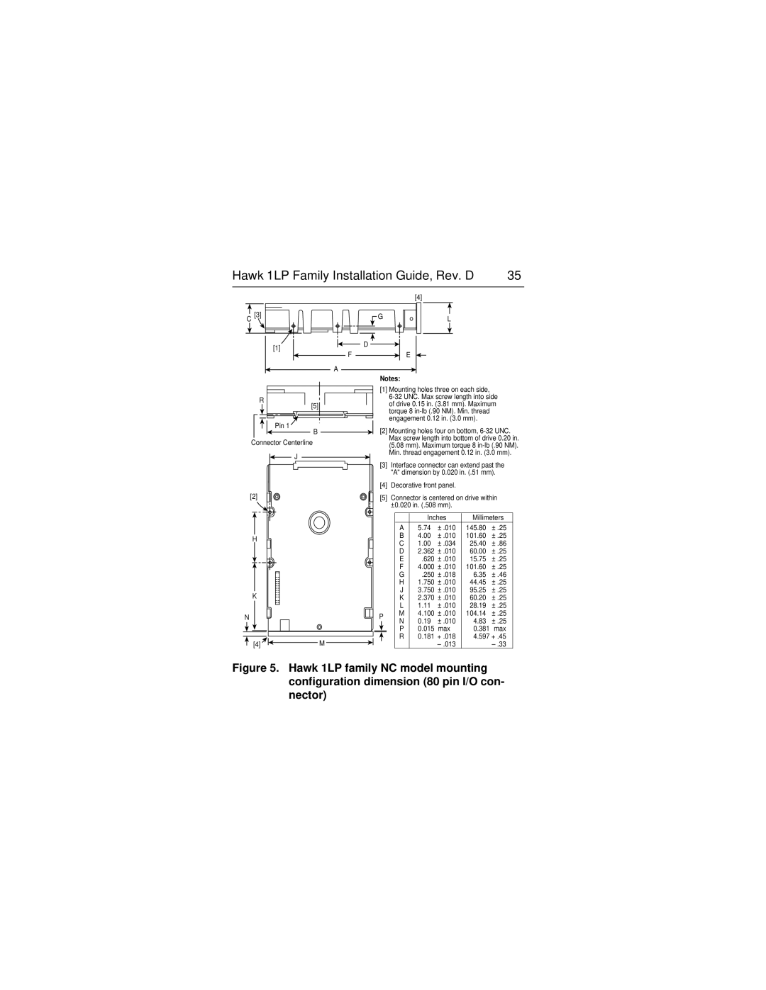
Hawk 1LP Family Installation Guide, Rev. D | 35 |
|
|
|
|
| [4] |
C | [3] | G | L |
|
| ||
| [1] | D |
|
|
|
| |
| F |
| E |
| A |
|
|
|
| Notes: |
|
R
[5]
Pin 1
B
Connector Centerline
J
[2]
H
K
N
[4]![]() M
M ![]()
![]()
[1]Mounting holes three on each side,
[2]Mounting holes four on bottom,
[3]Interface connector can extend past the "A" dimension by 0.020 in. (.51 mm).
[4]Decorative front panel.
[5]Connector is centered on drive within ±0.020 in. (.508 mm).
|
|
|
| Inches | Millimeters | |||
|
|
| A | 5.74 | ± .010 | 145.80 | ± .25 | |
|
|
| B | 4.00 | ± .010 | 101.60 | ± .25 | |
|
|
| C | 1.00 | ± .034 | 25.40 | ± .86 | |
|
|
| D | 2.362 | ± .010 | 60.00 | ± .25 | |
|
|
| E | .620 | ± .010 | 15.75 | ± .25 | |
|
|
| F | 4.000 | ± .010 | 101.60 | ± .25 | |
|
|
| G | .250 | ± .018 | 6.35 | ± .46 | |
|
|
| H | 1.750 | ± .010 | 44.45 | ± .25 | |
|
|
| J | 3.750 | ± .010 | 95.25 | ± .25 | |
|
|
| K | 2.370 | ± .010 | 60.20 | ± .25 | |
|
|
| L | 1.11 | ± .010 | 28.19 | ± .25 | |
P | M | 4.100 | ± .010 | 104.14 | ± .25 | |||
N | 0.19 | ± .010 | 4.83 | ± .25 | ||||
|
|
| ||||||
|
|
| P | 0.015 | max | 0.381 | max | |
|
|
| R | 0.181 | + .018 | 4.597 + .45 | ||
|
|
| ||||||
|
|
|
|
|
| |||
