38 | ST43401N/ND, ST43402ND User’s Manual, Rev. B |
To enable the feature, it is necessary to run an additional
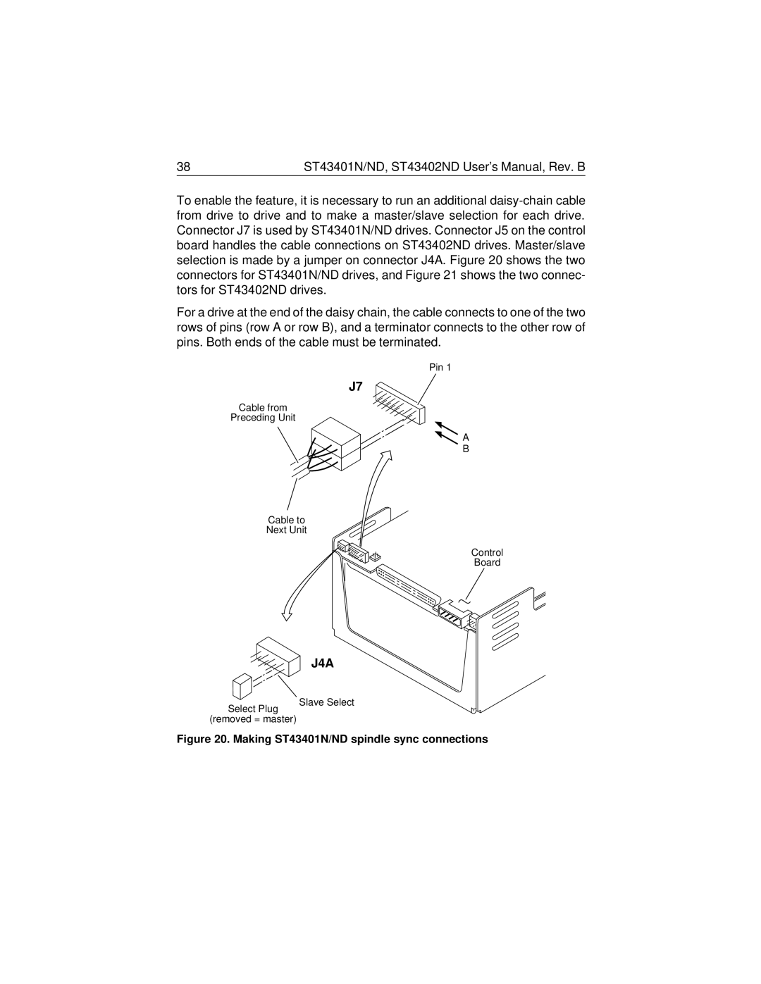
For a drive at the end of the daisy chain, the cable connects to one of the two rows of pins (row A or row B), and a terminator connects to the other row of pins. Both ends of the cable must be terminated.
Pin 1
J7
Cable from
Preceding Unit
![]() A
A
B
Cable to
Next Unit
Select Plug
Control
Board
J4A
Slave Select
(removed = master)