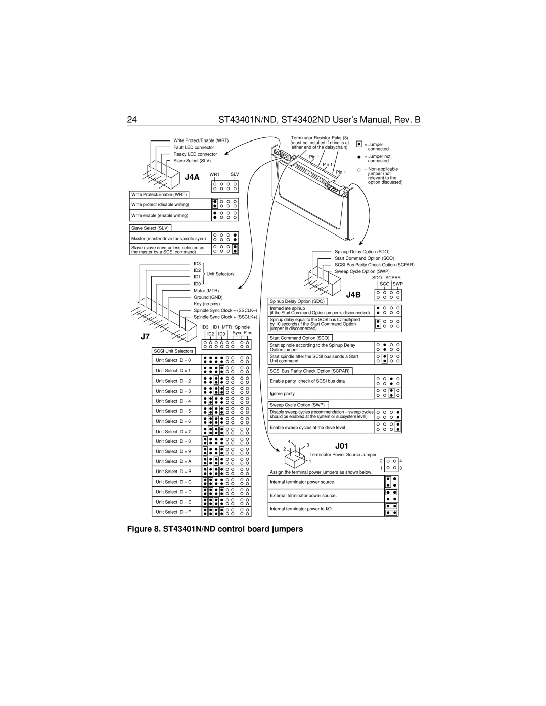
24 | ST43401N/ND, ST43402ND User’s Manual, Rev. B |
Write Protect/Enable (WRT)
Fault LED connector
Ready LED connector
Slave Select (SLV)
J4A WRT SLV
Write Protect/Enable (WRT)
Write protect (disable writing)
Write enable (enable writing)
Slave Select (SLV)
Master (master drive for spindle sync)
Terminator
Pin 1
Pin 1
Pin 1
=Jumper connected
=Jumper not connected
=
Slave (slave drive unless selected as the master by a SCSI command)
Spinup Delay Option (SDO)
Start Command Option (SCO)
ID3
ID2
ID1
ID0
Unit Selectors
SCSI Bus Parity Check Option (SCPAR)
Sweep Cycle Option (SWP)
SDO SCPAR
SCO SWP
Motor (MTR)
Ground (GND)
Key (no pins)
Spindle Sync Clock –
Spindle Sync Clock + (SSCLK+)
| ID3 ID1 MTR | Spindle |
J7 | ID2 ID0 | Sync Pins |
|
|
SCSI Unit Selectors
Unit Select ID = 0
Unit Select ID = 1
Unit Select ID = 2
Unit Select ID = 3
Unit Select ID = 4
Unit Select ID = 5
Unit Select ID = 6
Unit Select ID = 7
Unit Select ID = 8
Unit Select ID = 9
Unit Select ID = A
Unit Select ID = B
Unit Select ID = C
Unit Select ID = D
Unit Select ID = E
Unit Select ID = F
J4B
Spinup Delay Option (SDO)
Immediate spinup
(if the Start Command Option jumper is disconnected)
Spinup delay equal to the SCSI bus ID multiplied by 10 seconds (if the Start Command Option jumper is disconnected)
Start Command Option (SCO)
Start spindle according to the Spinup Delay
Option jumper
Start spindle after the SCSI bus sends a Start
Unit command
SCSI Bus Parity Check Option (SCPAR)
Enable parity check of SCSI bus data
Ignore parity
Sweep Cycle Option (SWP)
Disable sweep cycles (recommendation – sweep cycles should be enabled at the system or subsystem level)
Enable sweep cycles at the drive level
4 | J01 |
|
2 |
| |
3 |
|
|
Terminator Power Source Jumper |
| |
1 | 2 | 4 |
| 1 | 3 |
Assign the terminal power jumpers as shown below.
Internal terminator power source.
External terminator power source.
Internal terminator power to I/O.
