3.3Mounting considerations
•Use an elastic mounting material to protect drives so as to ensure that more shock can be absorbed.
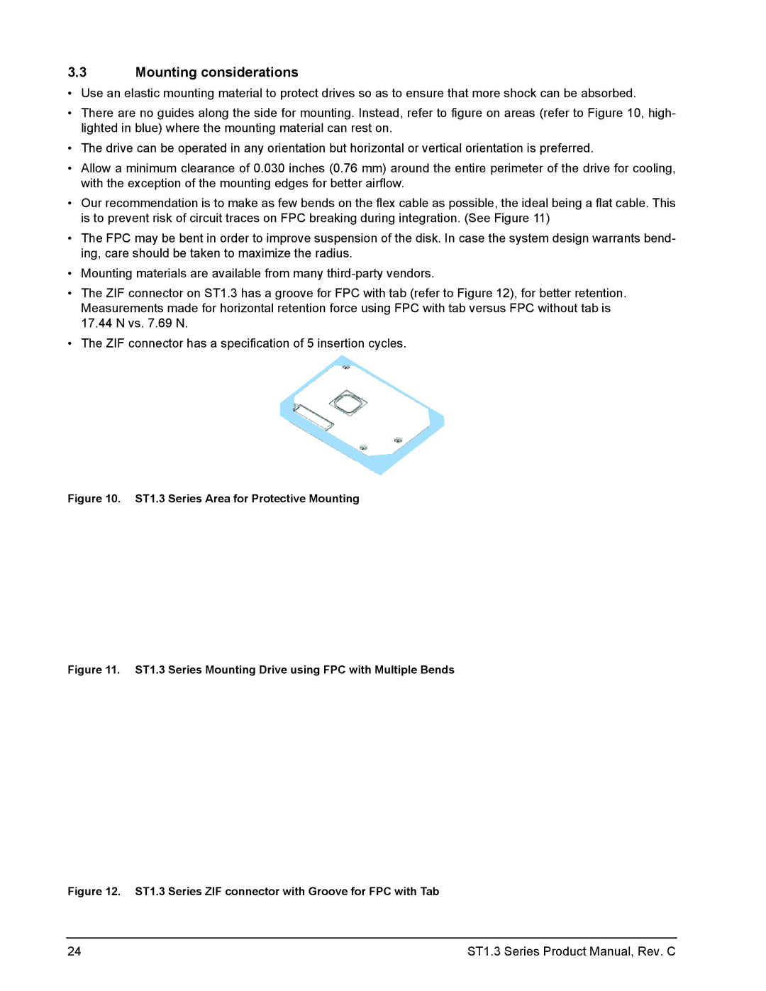
•There are no guides along the side for mounting. Instead, refer to figure on areas (refer to Figure 10, high- lighted in blue) where the mounting material can rest on.
•The drive can be operated in any orientation but horizontal or vertical orientation is preferred.
•Allow a minimum clearance of 0.030 inches (0.76 mm) around the entire perimeter of the drive for cooling, with the exception of the mounting edges for better airflow.
•Our recommendation is to make as few bends on the flex cable as possible, the ideal being a flat cable. This is to prevent risk of circuit traces on FPC breaking during integration. (See Figure 11)
•The FPC may be bent in order to improve suspension of the disk. In case the system design warrants bend- ing, care should be taken to maximize the radius.
•Mounting materials are available from many
•The ZIF connector on ST1.3 has a groove for FPC with tab (refer to Figure 12), for better retention. Measurements made for horizontal retention force using FPC with tab versus FPC without tab is 17.44 N vs. 7.69 N.
•The ZIF connector has a specification of 5 insertion cycles.
Figure 10. ST1.3 Series Area for Protective Mounting
Figure 11. ST1.3 Series Mounting Drive using FPC with Multiple Bends
Figure 12. ST1.3 Series ZIF connector with Groove for FPC with Tab
24 | ST1.3 Series Product Manual, Rev. C |
