4.0Interface description
These drives use the
For detailed information about the
4.1Connector interface signals and connector pins
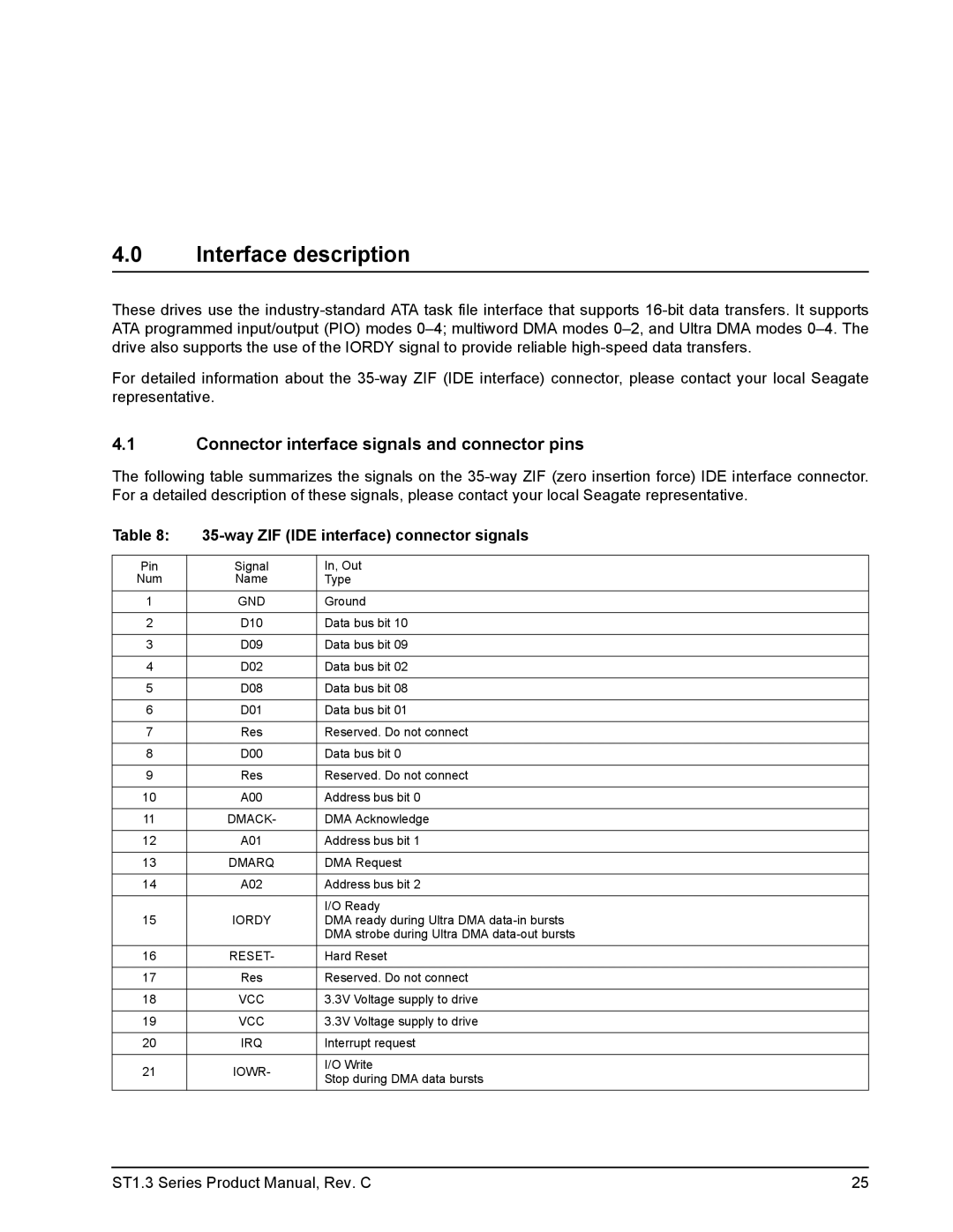
The following table summarizes the signals on the
Table 8: |
| ||
|
|
| |
Pin | Signal | In, Out | |
Num | Name | Type | |
1 | GND | Ground | |
|
|
| |
2 | D10 | Data bus bit 10 | |
|
|
| |
3 | D09 | Data bus bit 09 | |
|
|
| |
4 | D02 | Data bus bit 02 | |
|
|
| |
5 | D08 | Data bus bit 08 | |
|
|
| |
6 | D01 | Data bus bit 01 | |
|
|
| |
7 | Res | Reserved. Do not connect | |
|
|
| |
8 | D00 | Data bus bit 0 | |
|
|
| |
9 | Res | Reserved. Do not connect | |
|
|
| |
10 | A00 | Address bus bit 0 | |
|
|
| |
11 | DMACK- | DMA Acknowledge | |
|
|
| |
12 | A01 | Address bus bit 1 | |
|
|
| |
13 | DMARQ | DMA Request | |
|
|
| |
14 | A02 | Address bus bit 2 | |
|
|
| |
|
| I/O Ready | |
15 | IORDY | DMA ready during Ultra DMA | |
|
| DMA strobe during Ultra DMA | |
16 | RESET- | Hard Reset | |
|
|
| |
17 | Res | Reserved. Do not connect | |
|
|
| |
18 | VCC | 3.3V Voltage supply to drive | |
|
|
| |
19 | VCC | 3.3V Voltage supply to drive | |
|
|
| |
20 | IRQ | Interrupt request | |
|
|
| |
21 | IOWR- | I/O Write | |
Stop during DMA data bursts | |||
|
| ||
ST1.3 Series Product Manual, Rev. C | 25 |