A | ITEM | TABLE OF LOOSE | PARTS | QTY. | |
| A | Basic saw assembly | 1 | ||
| B | Owners | Manual | 1 | |
| C | Loose Parts Bag |
|
| |
|
| Containing the following | parts: |
| |
|
| Wing Nut | 1 | ||
|
| Screw, Truss Hd. | .................... | 1 | |
|
| Wrench, Hex "L" 1/8 | 1 | ||
| c |
|
|
|
|
|
| Bevel Indicator | 1 | ||
|
| Screw, | Pan Cross | 1 | |
|
| Washer | 17/64 x 1 x 1/16 | .................... | 1 |
|
| Bolt, Carriage | .................... | 1 | |
|
| Knob |
| 1 | |
|
| Clip Hose | 1 | ||
| D | Saw Table | 1 | ||
| D |
|
|
|
|
assembly
MOUNTING BAND SAW TO WORKBENCH
If band saw is to be used in a permanent location, it
should be fastened securely to a firm supporting sur- face such as a workbench.
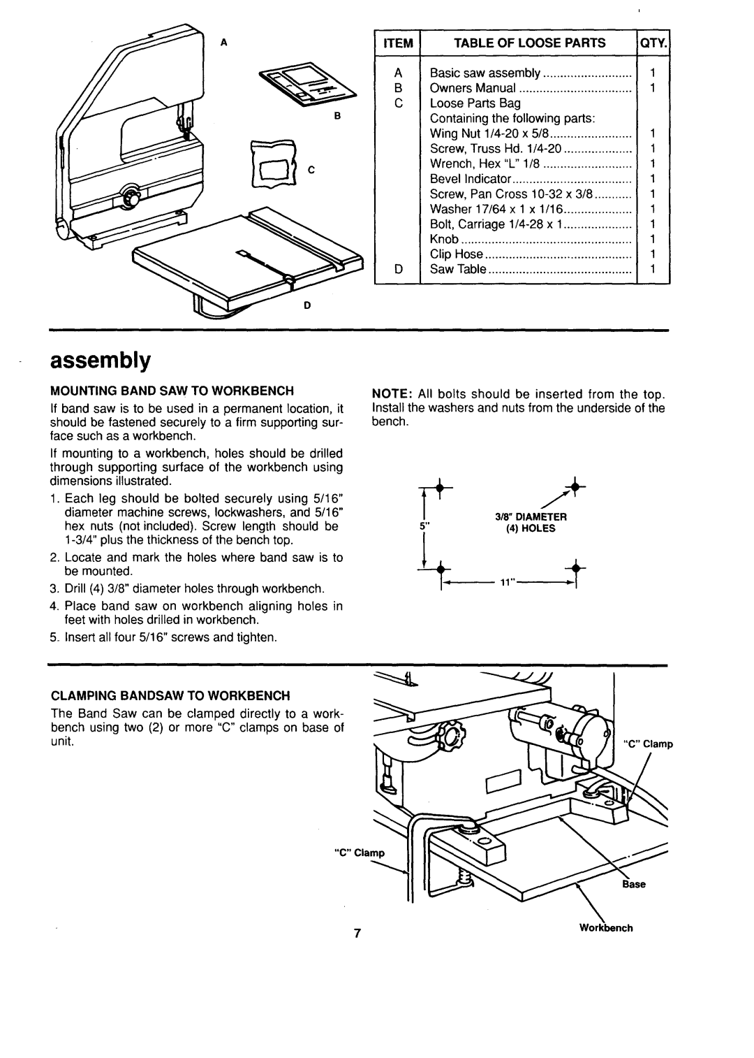
NOTE: All bolts should be inserted from the top. Install the washers and nuts from the underside of the bench.
If mounting to a workbench, holes should be drilled
through supporting surface of the workbench using dimensions illustrated.
1.Each leg should be bolted securely using 5/16" diameter machine screws, Iockwashers, and 5/16"
hex nuts (not included). Screw length should be
2.Locate and mark the holes where band saw is to be mounted.
3.Drill (4) 3/8" diameter holes through workbench.
4.Place band saw on workbench aligning holes in feet with holes drilled in workbench.
5.Insert all four 5/16" screws and tighten.
CLAMPING BANDSAW TO WORKBENCH
318" DIAMETE'_+R | |||
5" | (4) | HOLES | |
1 | |||
|
| ||
| 11" | ||
The Band Saw can be clamped directly to a work- bench using two (2) or more "C" clamps on base of unit.
"C" Clamp
"C" Clamp
Base