INSTALLING THE BLADE
WARNING: Push the
installing blade. | I |
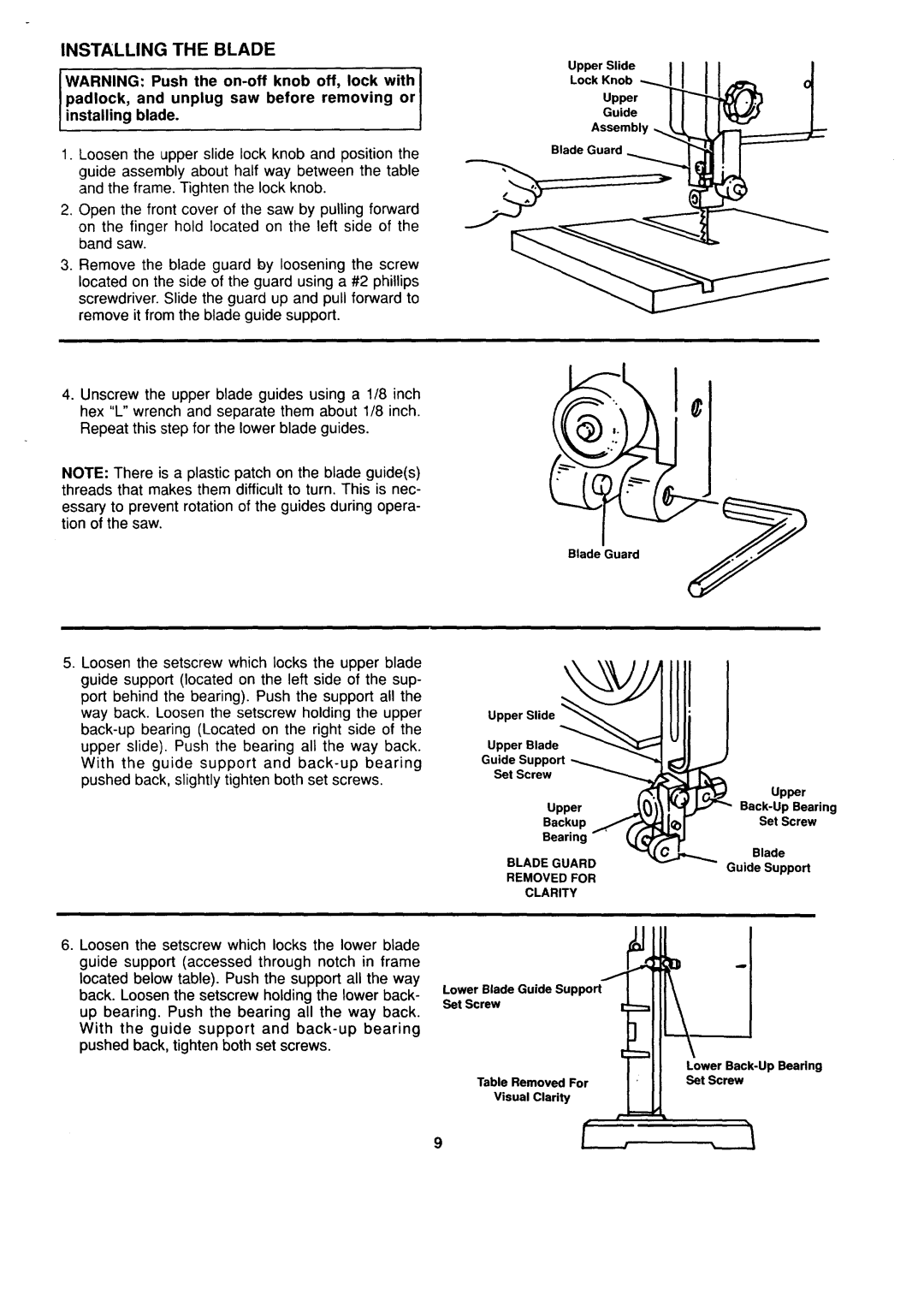
1.Loosen the upper slide lock knob and position the guide assembly about half way between the table and the frame. Tighten the lock knob.
2.Open the front cover of the saw by pulling forward
on the finger hold located on the left side of the band saw.
3.Remove the blade guard by loosening the screw located on the side of the guard using a #2 phillips screwdriver. Slide the guard up and pull forward to remove it from the blade guide support.
4.Unscrew the upper blade guides using a 1/8 inch hex "L" wrench and separate them about 1/8 inch. Repeat this step for the lower blade guides.
NOTE: There is a plastic patch on the blade guide(s) threads that makes them difficult to turn. This is nec-
essary to prevent rotation of the guides during opera- tion of the saw.
5.Loosen the setscrew which locks the upper blade
guide support (located on the left side of the sup- port behind the bearing). Push the support all the way back. Loosen the setscrew holding the upper
Upper Slide
Lock Knob
Upper
Guide
Assembly
Blade Guard
Blade Guard
Upper Slide
Upper Blade
Guide Support
Set Screw
Upper
Backup
Bearing
BLADEGUARD
REMOVED FOR
CLARITY
Upper
Set Screw
Blade
Guide Support
6.Loosen the setscrew which locks the lower blade guide support (accessed through notch in frame located below table). Push the support all the way back. Loosen the setscrew holding the lower back- up bearing. Push the bearing all the way back. With the guide support and
Lower Blade Guide Support Set Screw
Table Removed For
Visual Clarity
Lower
9