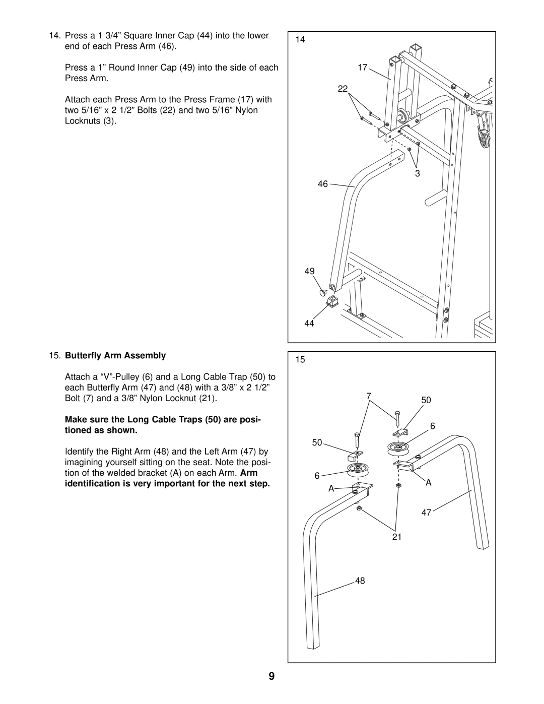
14.Press a 1 3/4” Square Inner Cap (44) into the lower end of each Press Arm (46).
Press a 1” Round Inner Cap (49) into the side of each Press Arm.
Attach each Press Arm to the Press Frame (17) with two 5/16” x 2 1/2” Bolts (22) and two 5/16” Nylon Locknuts (3).
15.Butterfly Arm Assembly
Attach a
Make sure the Long Cable Traps (50) are posi- tioned as shown.
Identify the Right Arm (48) and the Left Arm (47) by imagining yourself sitting on the seat. Note the posi- tion of the welded bracket (A) on each Arm. Arm identification is very important for the next step.
14 |
|
|
| 17 |
|
| 22 |
|
|
| 3 |
46 |
|
|
49 |
|
|
44 |
|
|
15 |
|
|
| 7 | 50 |
|
| |
|
| 6 |
50 |
|
|
6 |
| A |
A |
| |
|
| |
|
| 47 |
|
| 21 |
| 48 |
|
9
