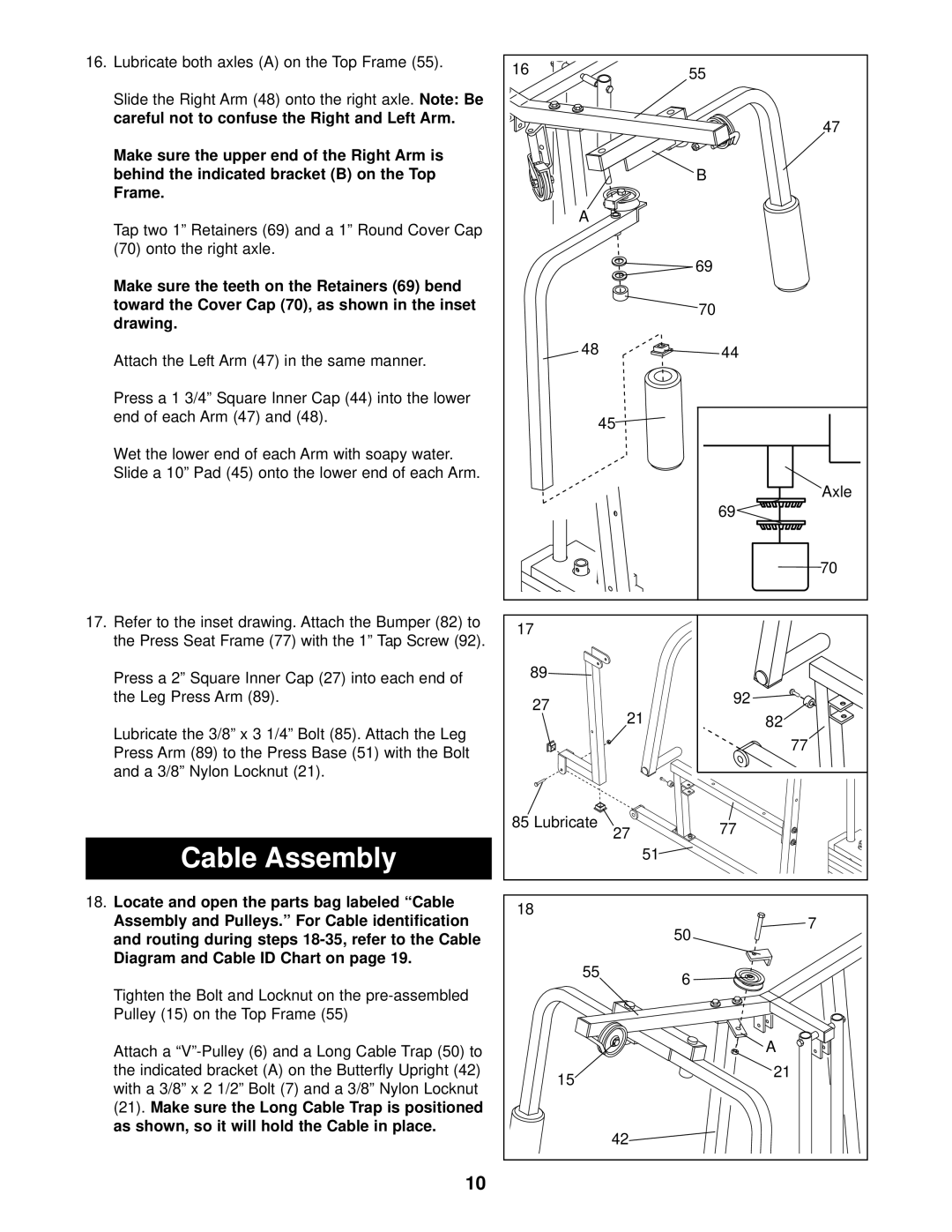
16.Lubricate both axles (A) on the Top Frame (55).
Slide the Right Arm (48) onto the right axle. Note: Be careful not to confuse the Right and Left Arm.
Make sure the upper end of the Right Arm is behind the indicated bracket (B) on the Top Frame.
Tap two 1” Retainers (69) and a 1” Round Cover Cap (70) onto the right axle.
Make sure the teeth on the Retainers (69) bend toward the Cover Cap (70), as shown in the inset drawing.
Attach the Left Arm (47) in the same manner.
Press a 1 3/4” Square Inner Cap (44) into the lower end of each Arm (47) and (48).
Wet the lower end of each Arm with soapy water. Slide a 10” Pad (45) onto the lower end of each Arm.
17.Refer to the inset drawing. Attach the Bumper (82) to the Press Seat Frame (77) with the 1” Tap Screw (92).
Press a 2” Square Inner Cap (27) into each end of the Leg Press Arm (89).
Lubricate the 3/8” x 3 1/4” Bolt (85). Attach the Leg Press Arm (89) to the Press Base (51) with the Bolt and a 3/8” Nylon Locknut (21).
Cable Assembly
18.Locate and open the parts bag labeled “Cable Assembly and Pulleys.” For Cable identification and routing during steps
Tighten the Bolt and Locknut on the
Attach a
16 | 55 | |
| ||
| 47 | |
| B | |
A |
| |
| 69 | |
| 70 | |
48 | 44 | |
45 |
| |
| Axle | |
| 69 | |
| 70 | |
17 |
| |
89 |
| |
27 | 92 | |
| ||
21 | 82 | |
| 77 | |
85 Lubricate | 77 | |
27 | ||
| ||
51 |
| |
18 | 7 | |
| ||
| 50 | |
55 | 6 | |
| ||
| A | |
15 | 21 | |
| ||
42 |
|
10