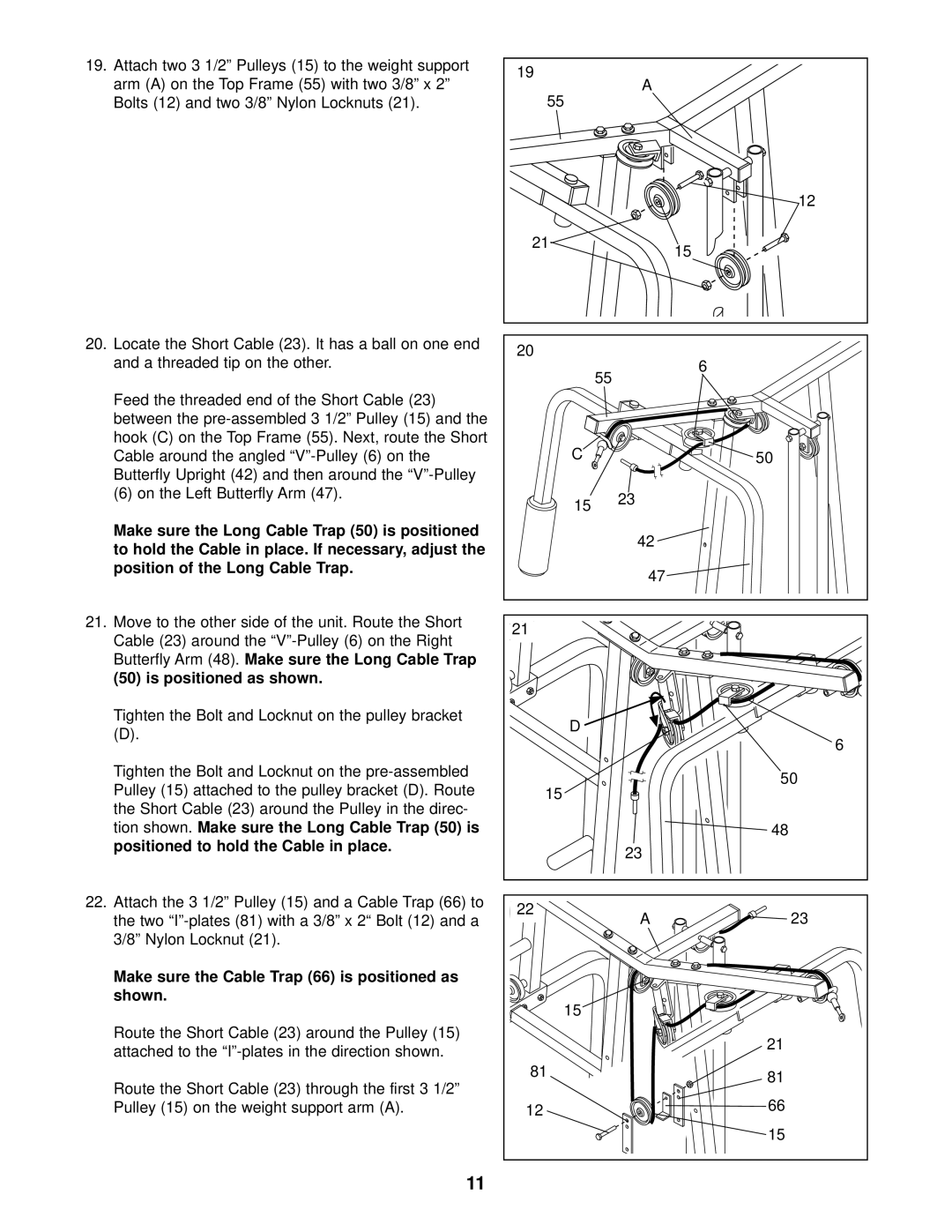
19.Attach two 3 1/2” Pulleys (15) to the weight support arm (A) on the Top Frame (55) with two 3/8” x 2” Bolts (12) and two 3/8” Nylon Locknuts (21).
20.Locate the Short Cable (23). It has a ball on one end and a threaded tip on the other.
Feed the threaded end of the Short Cable (23) between the
(6) on the Left Butterfly Arm (47).
Make sure the Long Cable Trap (50) is positioned to hold the Cable in place. If necessary, adjust the position of the Long Cable Trap.
21.Move to the other side of the unit. Route the Short Cable (23) around the
Tighten the Bolt and Locknut on the pulley bracket
(D).
Tighten the Bolt and Locknut on the
22.Attach the 3 1/2” Pulley (15) and a Cable Trap (66) to the two
Make sure the Cable Trap (66) is positioned as shown.
Route the Short Cable (23) around the Pulley (15) attached to the
Route the Short Cable (23) through the first 3 1/2” Pulley (15) on the weight support arm (A).
19 | A |
|
55 |
| |
|
| |
|
| 12 |
21 |
| 15 |
|
| |
20 |
| 6 |
| 55 | |
|
| |
C |
| 50 |
15 | 23 |
|
|
| |
| 42 |
|
| 47 |
|
21 |
|
|
D |
|
|
|
| 6 |
15 |
| 50 |
|
| |
|
| 48 |
| 23 |
|
22 | A | 23 |
| ||
15 |
|
|
|
| 21 |
81 |
| 81 |
|
| |
12 |
| 66 |
|
| |
|
| 15 |
11