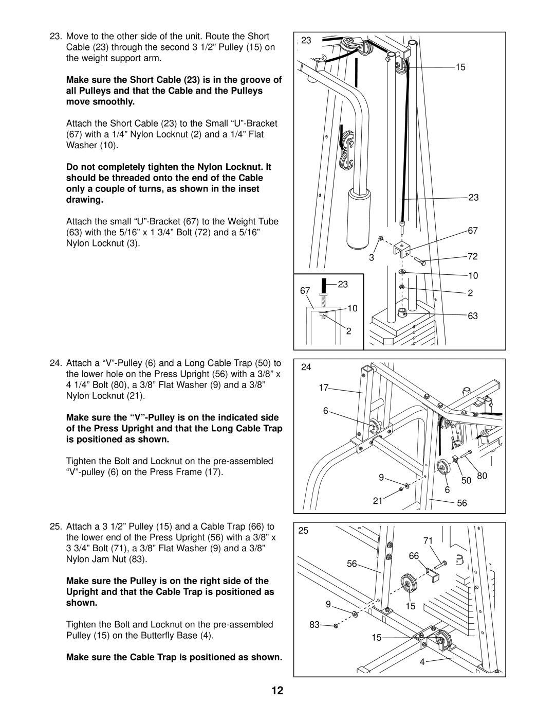
23.Move to the other side of the unit. Route the Short Cable (23) through the second 3 1/2” Pulley (15) on the weight support arm.
Make sure the Short Cable (23) is in the groove of all Pulleys and that the Cable and the Pulleys move smoothly.
Attach the Short Cable (23) to the Small
(67)with a 1/4” Nylon Locknut (2) and a 1/4” Flat Washer (10).
Do not completely tighten the Nylon Locknut. It should be threaded onto the end of the Cable only a couple of turns, as shown in the inset drawing.
Attach the small
(63)with the 5/16” x 1 3/4” Bolt (72) and a 5/16” Nylon Locknut (3).
24.Attach a
Make sure the
Tighten the Bolt and Locknut on the
25.Attach a 3 1/2” Pulley (15) and a Cable Trap (66) to the lower end of the Press Upright (56) with a 3/8” x 3 3/4” Bolt (71), a 3/8” Flat Washer (9) and a 3/8” Nylon Jam Nut (83).
Make sure the Pulley is on the right side of the Upright and that the Cable Trap is positioned as shown.
Tighten the Bolt and Locknut on the
Make sure the Cable Trap is positioned as shown.
23 |
|
|
| 15 |
|
| 23 | |
| 67 | |
3 | 72 | |
23 | 10 | |
|
| |
67 | 2 |
|
10 | 63 | |
| ||
2 |
|
|
24 |
|
|
17 |
|
|
6 |
|
|
9 | 50 | 80 |
|
| |
| 6 |
|
21 | 56 |
|
25 | 71 |
|
|
| |
56 | 66 |
|
|
| |
9 | 15 |
|
83 |
|
|
15 |
|
|
| 4 |
|
12
