OPERATION
WARNING! Relieve hydraulic pressure prior to doing any maintenance or repair work on the Implement. Place the Implement on the ground or securely blocked up, disengage the PTO, and turn off the tractor engine. Push and pull the Remote Cylinder lever in and out several times prior to starting any maintenance or repair work.
7. DRIVELINE ATTACHMENT
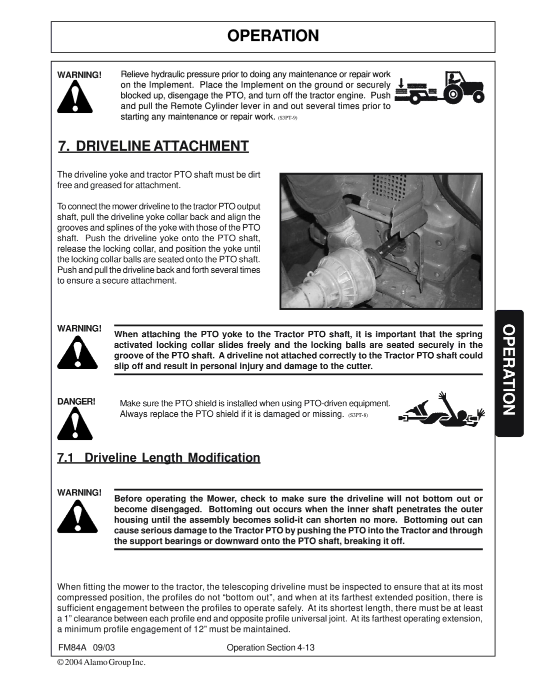
The driveline yoke and tractor PTO shaft must be dirt free and greased for attachment.
To connect the mower driveline to the tractor PTO output shaft, pull the driveline yoke collar back and align the grooves and splines of the yoke with those of the PTO shaft. Push the driveline yoke onto the PTO shaft, release the locking collar, and position the yoke until the locking collar balls are seated onto the PTO shaft. Push and pull the driveline back and forth several times to ensure a secure attachment.
WARNING! When attaching the PTO yoke to the Tractor PTO shaft, it is important that the spring activated locking collar slides freely and the locking balls are seated securely in the groove of the PTO shaft. A driveline not attached correctly to the Tractor PTO shaft could slip off and result in personal injury and damage to the cutter.
DANGER! | Make sure the PTO shield is installed when using |
| Always replace the PTO shield if it is damaged or missing. |
7.1 Driveline Length Modification
WARNING! Before operating the Mower, check to make sure the driveline will not bottom out or become disengaged. Bottoming out occurs when the inner shaft penetrates the outer housing until the assembly becomes
When fitting the mower to the tractor, the telescoping driveline must be inspected to ensure that at its most compressed position, the profiles do not “bottom out”, and when at its farthest extended position, there is sufficient engagement between the profiles to operate safely. At its shortest length, there must be at least a 1” clearance between each profile end and opposite profile universal joint. At its farthest operating extension, a minimum profile engagement of 12” must be maintained.
FM84A 09/03 | Operation Section |
© 2004 Alamo Group Inc.