MAINTENANCE
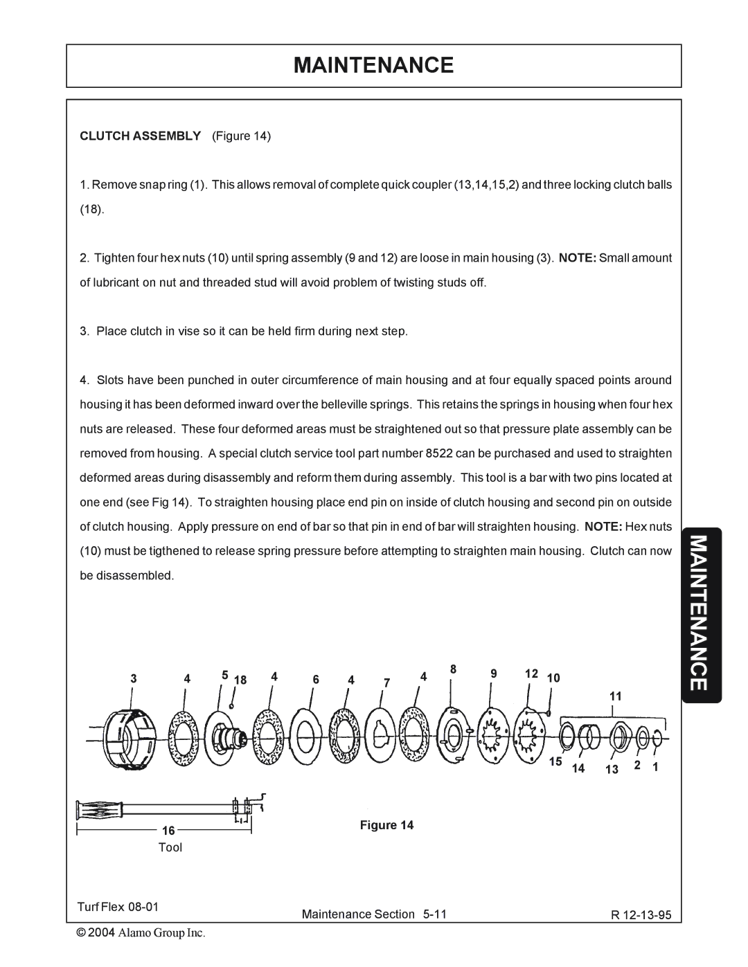
CLUTCH ASSEMBLY (Figure 14)
1.Remove snap ring (1). This allows removal of complete quick coupler (13,14,15,2) and three locking clutch balls (18).
2.Tighten four hex nuts (10) until spring assembly (9 and 12) are loose in main housing (3). NOTE: Small amount of lubricant on nut and threaded stud will avoid problem of twisting studs off.
3.Place clutch in vise so it can be held firm during next step.
4.Slots have been punched in outer circumference of main housing and at four equally spaced points around housing it has been deformed inward over the belleville springs. This retains the springs in housing when four hex nuts are released. These four deformed areas must be straightened out so that pressure plate assembly can be removed from housing. A special clutch service tool part number 8522 can be purchased and used to straighten deformed areas during disassembly and reform them during assembly. This tool is a bar with two pins located at one end (see Fig 14). To straighten housing place end pin on inside of clutch housing and second pin on outside of clutch housing. Apply pressure on end of bar so that pin in end of bar will straighten housing. NOTE: Hex nuts (10) must be tigthened to release spring pressure before attempting to straighten main housing. Clutch can now be disassembled.
3 | 4 | 5 18 | 4 | 6 | 4 | 7 | 4 | 8 | 9 | 12 | 10 |
|
|
|
|
|
| 11 |
|
| |||||||||||
|
|
|
|
|
|
|
|
|
|
|
|
|
|
| |
|
|
|
|
|
|
|
|
|
|
| 15 | 14 | 13 | 2 | 1 |
16 |
|
|
|
|
| Figure 14 |
|
|
|
|
|
|
|
|
|
|
|
|
|
|
|
|
|
|
|
|
|
|
|
| |
Tool |
|
|
|
|
|
|
|
|
|
|
|
|
|
|
|
Turf Flex |
|
|
| Maintenance Section |
|
|
|
|
| R | |||||
|
|
|
|
|
|
|
|
| |||||||
© 2004 Alamo Group Inc.