ASSEMBLY
ASSEMBLY
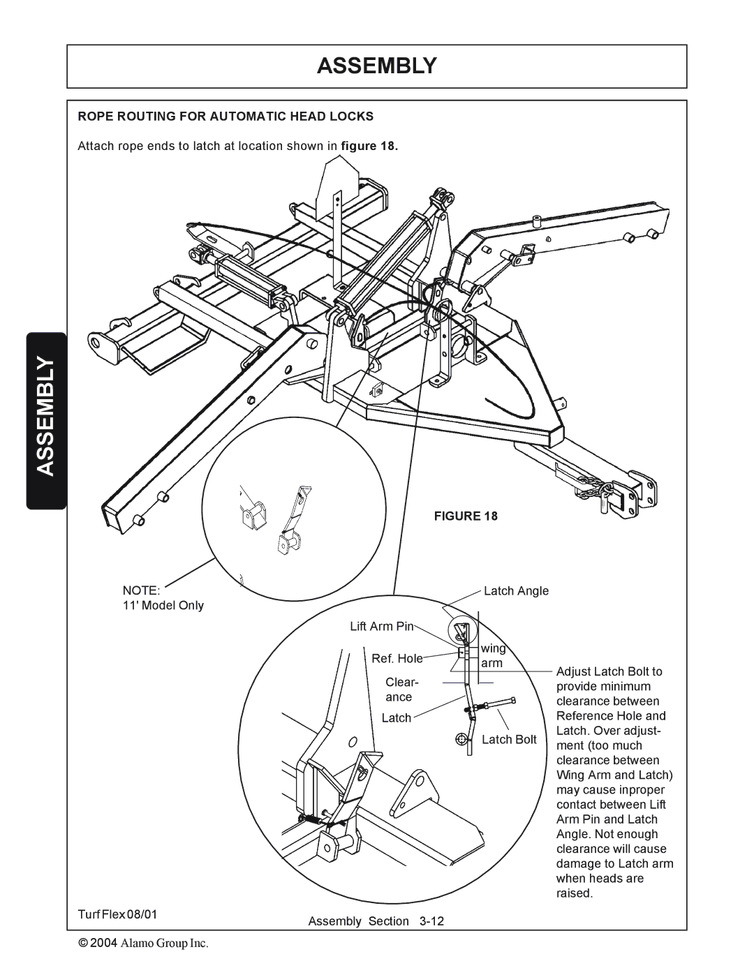
ROPE ROUTING FOR AUTOMATIC HEAD LOCKS
Attach rope ends to latch at location shown in figure 18.
FIGURE 18
NOTE: |
|
| Latch Angle |
| |
11' Model Only |
|
|
|
|
|
Lift Arm Pin |
|
|
|
|
|
Ref. Hole |
|
| wing |
| |
|
| arm | Adjust Latch Bolt to | ||
|
|
| |||
Clear- |
|
|
|
| |
|
|
|
| provide minimum | |
|
|
|
| ||
ance |
|
|
|
| |
|
|
|
| clearance between | |
Latch |
|
|
|
| Reference Hole and |
|
|
| Latch Bolt | Latch. Over adjust- | |
|
|
| ment (too much | ||
|
|
|
|
| |
|
|
|
|
| clearance between |
|
|
|
|
| Wing Arm and Latch) |
|
|
|
|
| may cause inproper |
|
|
|
|
| contact between Lift |
|
|
|
|
| Arm Pin and Latch |
|
|
|
|
| Angle. Not enough |
|
|
|
|
| clearance will cause |
|
|
|
|
| damage to Latch arm |
|
|
|
|
| when heads are |
|
|
|
|
| raised. |
Turf Flex 08/01 | Assembly Section |
| |
© 2004 Alamo Group Inc. |
|