ASSEMBLY
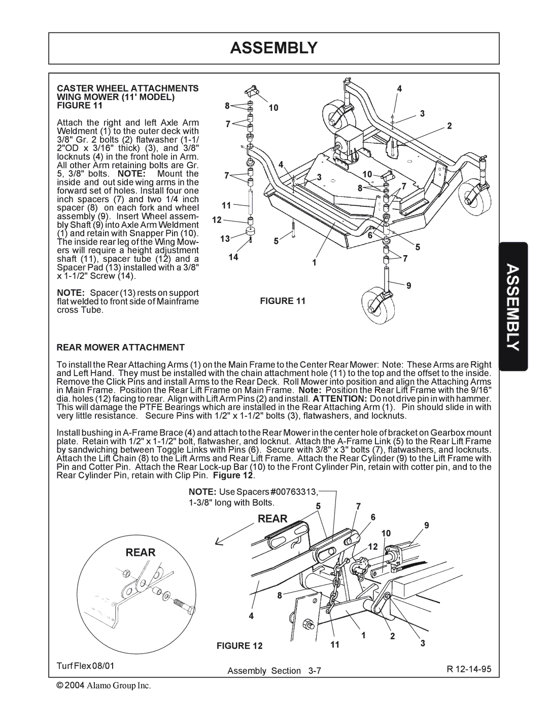
CASTER WHEEL ATTACHMENTS WING MOWER (11' MODEL) FIGURE 11
Attach the right and left Axle Arm Weldment (1) to the outer deck with 3/8" Gr. 2 bolts (2) flatwasher
(1)and retain with Snapper Pin (10). The inside rear leg of the Wing Mow- ers will require a height adjustment shaft (11), spacer tube (12) and a Spacer Pad (13) installed with a 3/8" x
NOTE: Spacer (13) rests on support flat welded to front side of Mainframe cross Tube.
REAR MOWER ATTACHMENT
|
|
| 4 |
8 | 10 |
| 3 |
7 |
|
| |
|
| 2 | |
7 | 4 | 10 |
|
3 | 7 | ||
|
| 8 | |
11 |
|
|
|
12 |
|
|
|
13 | 5 | 6 | 5 |
| |||
14 |
|
| |
1 |
| 7 | |
|
|
|
9
FIGURE 11
ASSEMBLY
To install the Rear Attaching Arms (1) on the Main Frame to the Center Rear Mower: Note: These Arms are Right and Left Hand. They must be installed with the chain attachment hole (11) to the top and the offset to the inside. Remove the Click Pins and install Arms to the Rear Deck. Roll Mower into position and align the Attaching Arms in Main Frame. Position the Rear Lift Frame on Main Frame. Note: Position the Rear Lift Frame with the 9/16" dia. holes (12) facing to rear. Align with Lift Arm Pins (2) and install. ATTENTION: Do not drive pin in with hammer. This will damage the PTFE Bearings which are installed in the Rear Attaching Arm (1). Pin should slide in with very little resistance. Secure Pins with 1/2" x
Install bushing in
| NOTE: Use Spacers #00763313, |
|
|
| |
| 5 | 7 |
|
| |
| REAR | 6 |
| ||
|
|
| 9 | ||
|
|
|
| 10 | |
|
|
|
|
| |
| REAR |
|
| 12 |
|
|
|
|
|
| |
| 8 |
|
|
|
|
| 4 |
|
|
|
|
| FIGURE 12 | 11 | 1 | 2 | 3 |
|
|
| |||
Turf Flex 08/01 | Assembly Section |
|
| R | |
|
|
| |||
© 2004 Alamo Group Inc.