| Controlling the Monitor with a PC | |
|
| |
|
| |
|
| |
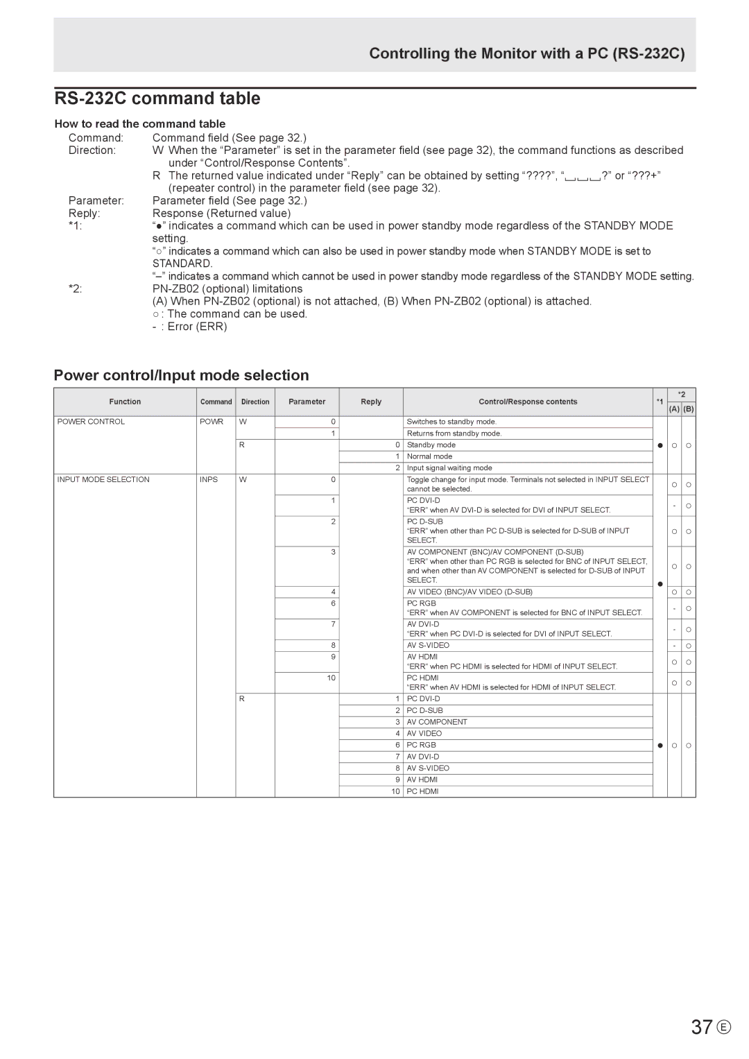
How to read the command table |
| |
Command: | Command field (See page 32.) |
|
Direction: | W When the “Parameter” is set in the parameter field (see page 32), the command functions as described | |
| under “Control/Response Contents”. |
|
| R The returned value indicated under “Reply” can be obtained by setting “????”, “ | ?” or “???+” |
| (repeater control) in the parameter field (see page 32). |
|
Parameter: | Parameter field (See page 32.) |
|
Reply: | Response (Returned value) |
|
*1: | “●” indicates a command which can be used in power standby mode regardless of the STANDBY MODE | |
| setting. |
|
| “○” indicates a command which can also be used in power standby mode when STANDBY MODE is set to | |
| STANDARD. |
|
| ||
*2: |
| |
| (A) When |
|
| ○ : The command can be used. |
|
|
| |
Power control/Input mode selection
Function | Command | Direction | Parameter |
| Reply | Control/Response contents | *1 |
| *2 | |
|
|
| ||||||||
(A) | (B) | |||||||||
|
|
|
|
|
|
|
|
|
|
|
POWER CONTROL | POWR | W |
| 0 |
| Switches to standby mode. |
|
|
|
|
|
|
|
| 1 |
| Returns from standby mode. | ● | ○ | ○ | |
|
| R |
|
| 0 | Standby mode | ||||
|
|
|
|
| 1 | Normal mode |
|
|
|
|
|
|
|
|
| 2 | Input signal waiting mode |
|
|
|
|
INPUT MODE SELECTION | INPS | W |
| 0 |
| Toggle change for input mode. Terminals not selected in INPUT SELECT |
| ○ |
| ○ |
|
|
|
|
|
| cannot be selected. |
|
| ||
|
|
|
| 1 |
| PC |
| - |
| ○ |
|
|
|
|
|
| “ERR” when AV |
|
| ||
|
|
|
| 2 |
| PC |
| ○ | ○ | |
|
|
|
|
|
| “ERR” when other than PC |
| |||
|
|
|
|
|
| SELECT. |
|
|
|
|
|
|
|
| 3 |
| AV COMPONENT (BNC)/AV COMPONENT |
|
|
|
|
|
|
|
|
|
| “ERR” when other than PC RGB is selected for BNC of INPUT SELECT, |
| ○ | ○ | |
|
|
|
|
|
| and when other than AV COMPONENT is selected for |
| |||
|
|
|
|
|
| SELECT. | ● |
|
|
|
|
|
|
| 4 |
| AV VIDEO (BNC)/AV VIDEO | ○ |
| ○ | |
|
|
|
| 6 |
| PC RGB |
| - |
| ○ |
|
|
|
|
|
| “ERR” when AV COMPONENT is selected for BNC of INPUT SELECT. |
|
| ||
|
|
|
| 7 |
| AV |
| - |
| ○ |
|
|
|
|
|
| “ERR” when PC |
|
| ||
|
|
|
| 8 |
| AV |
| - |
| ○ |
|
|
|
| 9 |
| AV HDMI |
| ○ | ○ | |
|
|
|
|
|
| “ERR” when PC HDMI is selected for HDMI of INPUT SELECT. |
| |||
|
|
|
| 10 |
| PC HDMI |
| ○ | ○ | |
|
|
|
|
|
| “ERR” when AV HDMI is selected for HDMI of INPUT SELECT. |
| |||
|
| R |
|
| 1 | PC |
|
|
|
|
|
|
|
|
| 2 | PC |
|
|
|
|
|
|
|
|
| 3 | AV COMPONENT |
|
|
|
|
|
|
|
|
| 4 | AV VIDEO | ● | ○ | ○ | |
|
|
|
|
| 6 | PC RGB | ||||
|
|
|
|
| 7 | AV |
|
|
|
|
|
|
|
|
| 8 | AV |
|
|
|
|
|
|
|
|
| 9 | AV HDMI |
|
|
|
|
|
|
|
|
| 10 | PC HDMI |
|
|
|
|