VR-654BD
PAN-EUROPEAN Unified Voltage
Introduction
Moisture condensation
Leave a space around the unit for sufficient ventilation
Contents
System Connections
Connecting AUDIO/VIDEO COmPONENTS
Copyright protection system
Video output resolution
Hdmi OUT
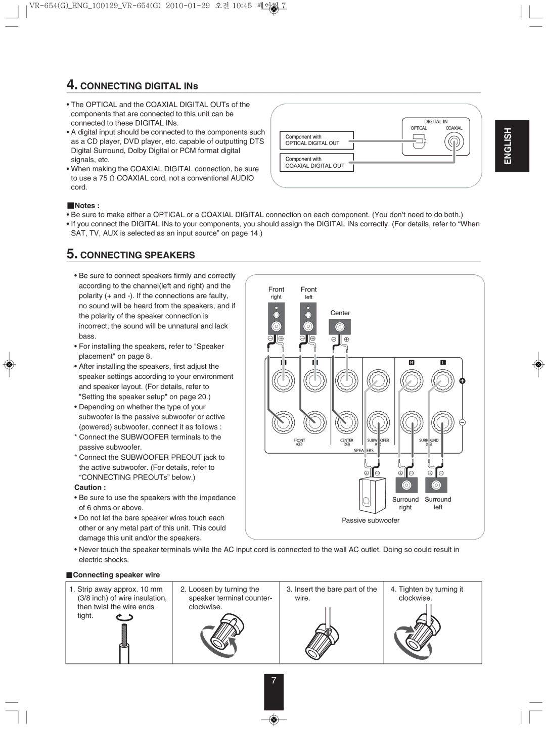
Connecting SPEAkERS
Connecting Digital INs
Connecting speaker wire
Speaker placement
Connecting PREOUTs
Connecting to NETWORk
Connecting for SYSTEm Control
Fluorescent Display PLAY/PAUSE
Front Panel Controls
Remote Sensor
OPEN/CLOSE
Universal Remote Controls
Repeat the above steps 1 to 4 for each of your components
EnteRInG a setUP coDe
Function Table of the Numbered Buttons
Enter a 3 digit code
LoADInG BAtteRIes
ReMote contRoL oPeRAtIon RAnGe
Basic Operation
When SAT, TV, AUx is selected as an input source
Listening to a PROGRAm Source
Adjusting the brightness of the fluorescent display
Operating the sleep timer
Surround modes
SURRoUnD soUnD
Drama
When selecting an input source other than BD/DVD
When selecting the BD/DVD
Movie
Select the desired menu using the Cursor UP/DOWN buttons
SYSTEm Setup
Setting the sound parameter
Turn the setup menu on
When selecting the LFE LFE level
When selecting the L.SYNC Lip-Sync
When selecting the D.m. Dual mono
When selecting the DRC Dynamic Range Control
Setting the speaker setup
About the speaker size
When selecting the SPEAkER Configuration
Press the OK button to confirm your selection
To cancel the test tone function, press the Return button
When selecting the Crossover Frequency
When selecting the Channel Level
About the speaker distance
Setting the Tone
①. Press the OK button to enter the tone adjustment mode
When selecting the SPEAkER Distance
Color system format
PReLIMInARY KnoWLeDGe ABoUt DIscs Playable disc types
Region code
Unplayable discs
PLAYABLe FILes
SYMBoL ABoUt InVALID oPeRAtIon
CARe AnD HAnDLInG oF DIscs
Avchd Advanced Video Codec High Definition
DeFInItIon oF teRMs
Jpeg Joint Photographic Experts Group
Before starting playback
Case of use of the NUmERIC buttons on the remote control
PLAYInG a DIsc
To start playback from the menu
Frame advance playback
To stop playback
To pause playback
Slow playback
Press the OK button
Displaying disc information
Playing the desired section of disc
During playback, press the GO to button
Playing in random order
Operations using disc menu, top menu, and Pop-up menu
Playing repeatedly
Playing a specific section repeatedly
Press the Popup button to exit
Switching the audio soundtrack
During playback, press the Popup Menu button
During playback, press the Audio button
Switching the camera angles
Switching the subtitles
During playback, press the Subtitle button
Playing secondary videoPicture in Picture
Press the Cursor Right button to enter the PIP mode menu
Virtual Package
When selecting the Play File
When selecting the Playlist Optical Disc or the USB
When selecting the Remove from Playlist
When selecting the Add To Playlist
To specify the time interval
Selecting an item in the play menu
Displaying file information
When entering file number
Playing the desired section of file
To change the effect on displaying pictures
When clearing the number entered
When selecting the Slide Show Effects
When selecting the Slide Show Delay
To control the music files
During playback of music files, press the OK button
OSD Menu Settings
SettInG tHe sYsteM
SettInG tHe DIsPLAY
SettInG tHe LAnGUAGe
SettInG tHe AUDIo
Parental Password Cancel
SettInG tHe PARentAL contRoL
When selecting the Parental Control or the Parental Level
When selecting the Parental Password
When selecting the manual
SettInG tHe netWoRK
When selecting the Wired
IP Settings
When selecting the manual or the Dynamic
When selecting the Network Test
When selecting the Off
Select the desired FM mode
Auto tuning
Manual tuning
Auto presetting
MEmORY BACkUP Function
Presetting radio stations
Tuning to preset stations
Tuning
Displaying RDS information
FM mode, press the Search Mode button
Listening to RDS BROADCASTSFm only
Searching for stations by program type
REmEDY
Troubleshooting Guide
REmOTE Control Unit PROBLEm
MAIN Unit AmPLIFIER Section PROBLEm
BD Player Section
Specifications
DBf
Fm Tuner Section
70 / 65 dB
Setup Code Table
Oceanic
Inno HIT
Nordmende
Interfunk
Sanyo
Sambers
Sampo
Samsung
City COM
Arcon
Astra
CH.MASTER
Preamble
GNU General Public License
English
No Warranty
How to Apply These Terms to Your New Programs
VR-654BD

