ASSEMBLY
Installing and Adjusting the Guide Bar and Saw Chain
|
| Brake lever |
|
|
| support arm |
|
|
|
| 57704 |
|
| 4. Remove the | |
|
| packing spacer. | |
| 35708 |
|
|
5. | Install the | Tensioner Pin |
|
guide bar. |
| ||
|
| ||
|
|
| Top of Bar |
|
| BAR |
|
|
| TIP |
|
|
| Bottom of Bar | |
|
|
| |
|
| 6. | Install the |
|
| chain loop. | |
| 35709 |
|
|
Spark Arrester
Hard starting or a gradual loss of performance can be caused by carbon deposits lodged in the spark arrester screen. For maximum performance, the spark arrester screen should be periodically cleaned as follows:
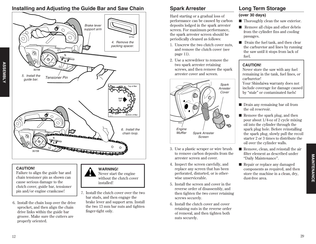
1.Unscrew the two clutch cover nuts, and remove the clutch cover (see page 11).
2.Use a screwdriver to remove the two spark arrester retaining screws, and then remove the spark arrester cover and screen.
| Spark |
| Arrester |
| Cover |
35722 |
|
Engine |
|
Muffler | Spark Arrester |
| Screen |
3. | Use a plastic scraper or wire brush |
| to remove carbon deposits from the |
| arrester screen and cover. |
4. | Inspect the screen carefully, and |
Long Term Storage
(over 30 days)
■Thoroughly clean the saw exterior.
■Remove all chips and other debris from the cylinder fins and cooling passages.
■Drain the fuel tank, and then clear the carburetor and lines by running the saw until it stops from lack of fuel.
CAUTION!
Never store the saw with any fuel remaining in the tank, fuel lines, or carburetor!
Your Shindaiwa warranty does not include coverage for damage caused by ÒstaleÓ or contaminated fuels!
■ Drain any remaining bar oil from |
the oil reservoir. |
■ Remove the spark plug, and then |
pour about |
oil into the cylinder through the |
spark plug hole. Before reinstalling |
the spark plug, slowly pull the recoil |
starter 2 or 3 times to distribute the |
oil over the cylinder walls. |
■ Remove, clean, and reinstall the air |
filter element as described under |
ÒDaily MaintenanceÕÕ. |
■ Repair or replace any damaged |
CAUTION!
Failure to align the guide bar and chain tensioner pin as shown can cause serious damage to the clutch cover, guide bar, tensioner pin and/or engine crankcase!
6.Install the chain loop over the drive sprocket, and then align the chain drive links within the guide bar groove. Make sure the cutters are properly oriented.
WARNING!
Never start the engine without the clutch cover installed!
7.Install the clutch cover over the two bar studs, and then engage the brake lever and support arm. Install the two 13 mm bar nuts and tighten
replace any screen that has been |
perforated, distorted, or is other- |
wise unserviceable. |
5. Install the screen and cover in the |
reverse order of disassembly, and |
then tighten the two cover retaining |
screws securely. |
6. Install the clutch cover and cover |
retaining nuts in the reverse order |
of removal, and then tighten both |
nuts securely. |
components as required, and then |
store the machine in a clean, dry, |
MAINTENANCE
12 | 29 |
