Teleperm m
Automation and Drives
Related catalogs
AS 488/TM automation systems
Teleperm M Process Control System
Introduction
AS 488/TM
Teleperm M Process Control System
Introduction
Overview
Automation systems
Migration strategy
Engineering
System bus
AS 488/TM
Classification in the Teleperm M system environment
Highlights
Limitations in communication
Non-migratable systems
Functions Highlights
Area of application
System properties
System architecture
System software
Commissioning
Functions
System architecture
System properties
AS 488/TM CPU
Technical Specifications Quantity breakdown
User function blocks
System software
Standard function blocks
Optional function blocks
Listing of Teleperm M standard function blocks Data blocks
Configuration
Blocks for analog and digital processing
Blocks for binary processing
PKF
PKM
AKS
AKE
Type Name Function Interface
Blocks for PLC/PLC coupling with PROFIBUS-AG/AG
Type Name Function For modules with Order No
Test blocks
Blocks for I/O modules with standardized display
Organization blocks
Commissioning terminal
Commissioning
Cable for connection of the commissioning terminal
If 962-COM serial interface module
Bus connection
Engineering with Prograf AS+
Automation systems released for Prograf AS+/NT
Technical Specifications Hardware requirements
Software requirements
PC components PCI for connection to Teleperm M system bus
Accessories
PC components ISA for connection to Teleperm M system bus
System architecture
AS 488 S cabinet system
AS 488 S Cabinet system
AS 488 S
Cabinet system
AS 488 S cabinet system
Scope of delivery of AS 488 S systems
Cables for connection of two I/O buses with versions 1
Power supply
Connection to CS 275 system bus with versions 5 to
System software
6DS9 207-8AA
Log IK PI
Teleperm M 19 cabinets
AS 488 K compact system
AS 488 K Compact system
AS 488 K
Compact system
AS 488 K compact system
Overview Ordering Data
Connection to CS 275 system bus
Teleperm M I/Os connection
Each 6DS4 400-8AB 6DS9 203-8CA
Bus components for single CS
Bus components for redundant CS
Introduction
AS 488 in Simatic design
Introduction
Technical Specifications
AS 488 in Simatic design
Coupling to PROFIBUS-PA
Coupling to other systems with DP interface
ET 200U
ET 200B
Overview CPU
Central processing unit
Monitoring
CPU
Backup battery
Power supply modules
PS 405 and PS 407 load power supplies
EXM 478 expansion module 6ES7 478-2AC00-0AC0
Connection of distributed I/Os
If 964-DP interface module
DP2-INI initialization C79451-A3496-D900
Connection to Teleperm M I/Os
EXM 478 expansion module
Connection to CS Connection to PROFIBUS-TM
TPM 478 interface module 6ES7 478-2DA01-0AC0
Migration rack
Packaging system
Overview UR2 rack
System software, documentation
Additional configuring tools
Simatic PCS 7 cabinet design
Cabinet packaging system
Simatic PCS 7 cabinet design
Mechanical design
Basic cabinet
Electrical design
Options for the electrical design
Load power supply for I/O modules
Power supply
ET 200M I/O unit
Hot swapping
AS 488/TM system unit
Simatic PCS 7 cabinet design
Migration packages
Migration of existing systems
General marginal conditions
Migration of existing systems
Migration of existing systems
Additive supplementary components and services
Scope of delivery and services
Migration packages
AS 488 S migration package
AS 488 S migration package
General marginal conditions/limitations
AS 488 K migration package
GWK-PAS-AS-UPAK488
AS 488 K migration package
MIG I migration rack
MIG II migration rack
Configuration possibilities for I/Os
MIG K migration rack
Retrofitting services
Check list prior to retrofitting
Migratable Teleperm M modules in AS 488/TM
Configuring lists
Migratable Teleperm M modules in AS 488/TM
Explanations for the column „Release
Explanations for the column „Remarks
Binary calculation modules
Coupling modules
Migration of existing systems
ET 200M packaging system
Connecting PROFIBUS-PA to AS 488/TM
Process I/Os
Process I/Os
TBX 478 interface module
Connecting Teleperm M I/Os
TBX 478 interface module 6ES7 478-2DX00-0AA0
Set of ribbon cables C79451-A3496-D2
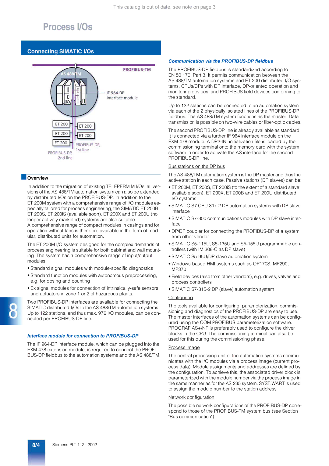
Communication via the PROFIBUS-DP fieldbus
Connecting Simatic I/Os
Interface module for connection to PROFIBUS-DP
PROFIBUS-DP quantity breakdown
COM Profibus
Driver blocks
Mode of operation
DP extensions for AS 488/TM
ET 200M
ET 200M packaging system
Components for both packaging systems
Simple packaging system with bus connectors
ET 200M modules
Temperature range Inputs, 14 bit, 20 ms conver
Temperature range Inputs, 16 outputs
SM 323 digital input/output modules Inputs, 8 outputs
Inputs, 8 outputs, extended
Ex digital input/output modules EEx ib
Ex I/O modules
Intrinsically-safe equipment which can be connected
Ex analog input/output modules EEx ib
Function and communications modules
Configuration and parameterization
Configuration limits when used on AS
ET 200S
ET 200S
6ES7 134-4FB50-0AB0
6ES7 134-4FB00-0AB0
6ES7 134-4LB00-0AB0
6ES7 134-4GB00-0AB0
ET 200U
ET 200X, ET 200U and ET 200B
ET 200B
IP 262 closed-loop control mod- ule
Siwarex M
Configuration Siwa driver block
Properties and application features of the PROFIBUS-PA
Connecting PROFIBUS-PA to AS 488/TM
Delivery forms
Teleperm M
Connection of PROFIBUS-PA using DP/PA link
Connection of PROFIBUS-PA using DP/PA coupler
Driver block Description
PROFIBUS-PA
Technical data DP/PA link IM DP/PA coupler Only
Technical Specifications Ordering Data
IM 157 interface module for 6ES7 157-0AA81-0XA0 DP/PA link
AS x88/TM-PA coupling soft 6DS5 130-8AA Ware, full license
Process I/Os
CS-L2 bridge
Bus communication
Transmission systems
Bus communication
Optical link module
Bus connector
Electrical bus terminal
Transmission media
Optical bus terminal OBT for Profibus
TPM 478 interface module
Configuring
Length ..... m
Standard remote bus cable V45466-D21-B35
In-house remote bus cable
Remote bus cable with addi- tional armoring
CS-L2 bridge
CS-L2 bridge
Performance data
Configuration Station addresses
CS-L2 bridge
PROFIBUS-TM
Central processing unit
PS 405 load power supply, 10 a 6ES7 405-0KA01-0AA0
TPM 478 interface module
Connection to PROFIBUS-TM Connection to CS
If 964-DP interface module 6ES7 964-2AA01-0AB0
Ordering Data Overview
Introduction AG-AG coupling software Serial coupling
Data couplings with other systems
Data couplings
Data couplings with other systems
10/2
Coupling with systems from other vendors
AG-AG coupling software
System couplings
10/3
AG/AG coupling with Simatic S5/S7 central controllers
PROFIBUS-AG/AG
10/4
AG/AG coupling software 6DS5 124-1AA
SDA
Serial coupling
Direct couplings
10/5
Transmission rate Max. cable length
10/6
Appendix
Software licenses
Appendix
Software
11/2
11/3
Information and order option
Internet and on CD-ROM
11/4
Internet, Training
Internet
Training Courses in the Training Center Karlsruhe
11/5
Order No. index