AS-Interface
Benefits
Introduction
Transmission technology
Overview Transmission method
Process or field communication
Configuration examples
Operating modes
System components
System components
Overview
More information
Technical specifications
Technical specifications
Addressing A/B slaves
Technique
A/B technique concept
AS-Interface master Communication cycle
CP 343-2 P
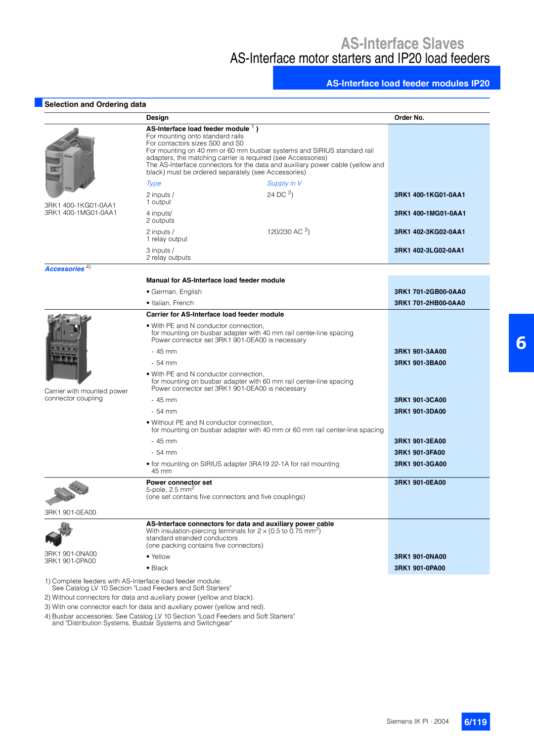
Selection and Ordering data
Design
Introduction
AS-Interface Safety at work
Safety included
Tested safety
AS-Interface safety monitors
Dimensional drawings
PNP
AS-Interface safe compact modules
SAP
UL, CSA
3RK1 901-1KA01
Design Order No K45F safe compact module 3RK1 205-0BQ00-0AA3
K45F Safe Compact Module
Schematics
Socket Assignment / data sheet / function
Logical assignments
Overview Application
AS-Interface position switches
Position switch with separate actuator
Position switch with tumbler
Design Order No
AS-Interface position switch, standard, with M12 connector
3SF3 243-0XX40-0BA1
3SF3 200-6XX03-0BA1
3SF3 200-6XX04-0BA1
3SF3 243-0XX00-0BA1
3SF2 150-1BF00-0BA1
AS-Interface cable-operated switches
Specifications
AS-Interface cable-operated switch
Standards
AS-Interface light curtains and light arrays for Category
Overview Benefits
Transmitter/receiver synchronization
3SF7 842-6BC01
3SF7 842-6BB00
3SF7 842-6BB01
3SF7 842-6BC00
3SF7 842-6EF00
Siguard Standard Light Curtain, 90 mm resolution
3SF7 842-6EE00
3SF7 842-6EE01
3SF7 842-6PG00
Design Order No Siguard Light Array
3SF7 842-6SE00
3SF7 842-6SE01
AS-Interface laser scanner LS4
Accessories
Further applications
LS4Soft operating software
Function principle
Pack 3RX9 307-0AA00
3SF7 834-6DD00
PIN
PIN1 PIN2 PIN3
LS4 laser scanner
AS-Interface Emergency Stop pushbuttons
User interface
Masters for Simatic S5
Ordering data
Parameter assignment
Masters for Simatic S7
Overview Design
6GK7 142-2AH00-0XA0
Profibus
Overview Application
6GK7 243-2AX01-0XA0
Mode of operation
For connection of Simatic S7-300
CP 343-2 P
CP 343-2 P 6GK7 343-2AH10-0XA0 Communications processor
Modules for operation in the field
LED diagnostic indication of the K60 compact module
K60 mounting plate
Digital I/O modules IP67 K60
K60 compact modules with up to eight digital inputs
K60 compact module
New products
AS-Interface Slaves
AS-Interface Slaves
Are not required Siemens IK PI ·
Sealing kit 3RK1 902-0AR00
Design Order No Digital I/O modules IP67 K60
AS-Interface M12 sealing caps 3RK1 901-1KA00
Distributor 3RK1 901-1NN00
IN1 IN2
Terminal assignment, input, pnp M12 socket
Singlecable
Terminal assignment, output, pnp M12 socket
Addressing
Digital I/O modules IP68 / IP69K K60R
Mounting
IP68 / IP69K tests
Connection
3RK1 400-1CR00-0AA3
Inputs/4 outputs IP68 / IP69K
3RK1 901-1NR00
IP67 round cable distributor
AS-i / Uaux Ribbon cable for
M12, passive without LED
Modules for operation in the field
Digital I/O modules IP67 K45
Mounting possibilities
For 3RK2 400-1BQ20-0AA3 Umin = 16.5
Put in a DC 12 / DC 13 typ
Cable, contacted through Grated seal seal shaped
Cable end piece 3RK1 901-1MN00
Design Order No Digital I/O modules IP67 K45
K45 mounting plate
3RK1 901-1PN00
Distributor 3RK1 901-1NN00 Siemens IK PI ·
Terminal assignment input, pnp M12 socket
Terminal assignment input, pnp M8 socket
Terminal assignment output, pnp M12 socket 24 V DC
Application module Comparison type K45 Order No Design
Digital I/O modules IP67 application modules
Advantages of the K45 compact modules
Application module decoding table K45
EMI
PNP NPN
EMI Eemi
Without LED
1 input/1 output
3RG9 001-0AJ00
Fold distributor passive
3RG9 001-0CB00
Operating voltage in accordance 26.5 to
Coupling modules
Dimensional drawings Application modules
Analog I/O modules IP67 K60
Modules for operation in the field
3RK1 207-3BQ40-0AA3
Design Order No Analog I/O modules IP67 K60
3RK1 207-1BQ40-0AA3
3RK1 107-1BQ40-0AA3
Pin assignment output module
Pin assignment input module
Order informationen of Kuhnke GmbH
Pneumatic I/O modules
PCB
Modules for operation in IP20 control cabinet
F90 module
LED diagnostics indication
Modules for operation in IP20 control cabinet
SlimLine Series
Removable terminals
Features
SlimLine
SlimLine modules of Series S22.5 and S45
Locking removable terminals
Technical specifications common to all SlimLine modules
Releasing removable terminals
Customer benefits
IN3
SlimLine S22.5
IN1
IN2
OUT2
OUT1
OUT2 OUT4
IN1 OUT1
IN2 OUT2
OUT1 OUT3
IN3/OUT3
SlimLine S45
IN1/OUT1
IN2/OUT2
200
AS-Interface Slaves
IN4
Plug-in lugs 3RP1
SlimLine S22.5 module
SlimLine S45 module
Sealable cap 3RP1
Typical circuit diagram for SlimLine S45
Typical circuit diagram for SlimLine S22.5
Eeee
Module F90
Built-in via terminal screws
Total current input in mA Input connection
AS-Interface Slaves
Design Order No F90 module
Dimensional drawings Schematics
Combicon connector set 3RX9 810-0AA00
Terminal assignment
Design Order No Flat module 3RK1 400-0CE00-0AA3
Flat module
AS-Interface communication modules
Special integrated solutions
OUT1 OUT2 OUT3 OUT4
Connection Connection pad
IN1 IN2 IN3 IN4
With gold-plated
Supply via AS
3RK1 400-1CD00-0AA2
Design Order No Inputs / 4 outputs
3RK1 400-0CD00-0AA3
3RK1 400-0CD01-0AA3
Counter modules
Modules with special functions
Design Order No Counter module
Modules with special functions
100
Earth fault detection modules
101
102
Protection level Up
Installation guidelines Nominal discharge current isn
Overvoltage protection module
103
Overvoltage protection module 3RK1 901-1GA00
104
105
AS-Interface motor starters and IP65/67 load feeders
AS-Interface compact starters IP65 400 V AC
106
Display characteristics
Outputs
107
Inputs
DO1
Tripped signal
108
DS/RS EDS/ERS
109
110
111
Connector set for power infeed, 9-pole
112
Connector pin assignment digital inputs Y assignment
Connector pin assignment power connector
Brake
AS-Interface motor starters IP67 24 V DC
113
Quick stop function
114
115
116
Ecofast motor and soft starter
AS-Interface load feeder module
AS-Interface motor starters and IP20 load feeders
AS-Interface load feeder modules IP20
117
Inputs
118
119
Typical control circuits
120
AS-Interface load feeder module
Sirius soft starters
121
Design Order No Sirius Soft Starter
122
Signum pushbuttons and indicator lights
AS-Interface F-Adapter for Emergency Stop command devices
123
AS-Interface enclosure
AS-Interface enclosure
AS-Interface customized enclosures and front panel modules
124
Options
125
AS-Interface front panel module
126
Order form for AS-Interface housing
Order form AS-Interface front panel modules
Configuration
127
128
129
Code for design/key removal position of locks
130
131
132
133
AS-Interface LED displays
Each LOGO! now connectable to the AS-Interface system -new
AS-Interface for Logo
134
135
Earth fault detection
136
Power supply units IP20
CE, UL, CSA
137
3RX9 305-1AA00 3RX9 306-1AA00
35 15 mm and S7 rail 35 x 7.5 mm Special function
138
Dual output 4 a
Design Order No AS-Interface IP20 power supply unit
139
135 54,6 105
140
141
Power supply units IP65
Single output 230 AC 3RX9 311-0AA00 24 DC 6EP1 632-1AL01
142
TPE special version
Transmission media
AS-Interface shaped cable
143
144
Benefits Repeaters
System components and accessories
Repeater/Extender
145
Design Repeaters
146
3RK1 904-2AB01
AS-Interface addressing and diagnostic unit
Addressing units
147
Addressing cable with jack plug Z231A
Addressing cable with M12 female connector 3RX1
148
Online statistics
Diagnostic units
149
Trace modus Test report
150
151
Miscellaneous accessories
Way distributor
Documentation
Brochures
152