eWON4002™
Installation Guide
ver 2 . 04
Positions | Mode |
|
|
OFF | RS232 |
| |
ON |
|
|
|
OFF | RS422, RS485 |
| |
| WITHOUT polarisation and termination resistors |
ON |
|
|
|
OFF | RS422, RS485 |
| |
ON | WITH polarisation and termination resistors |
| |
| |
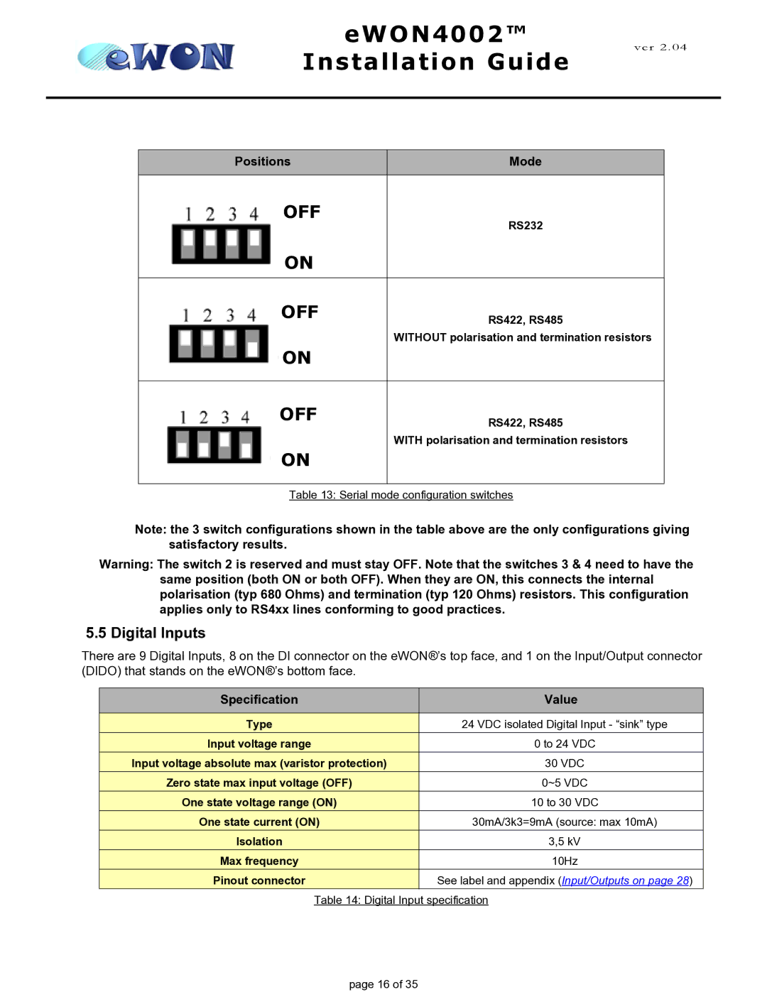
Table 13: Serial mode configuration switches | |
Note: the 3 switch configurations shown in the table above are the only configurations giving satisfactory results.
Warning: The switch 2 is reserved and must stay OFF. Note that the switches 3 & 4 need to have the same position (both ON or both OFF). When they are ON, this connects the internal polarisation (typ 680 Ohms) and termination (typ 120 Ohms) resistors. This configuration applies only to RS4xx lines conforming to good practices.
5.5 Digital Inputs
There are 9 Digital Inputs, 8 on the DI connector on the eWON®’s top face, and 1 on the Input/Output connector (DIDO) that stands on the eWON®’s bottom face.
Specification | Value |
|
|
Type | 24 VDC isolated Digital Input - “sink” type |
Input voltage range | 0 to 24 VDC |
Input voltage absolute max (varistor protection) | 30 VDC |
Zero state max input voltage (OFF) | 0~5 VDC |
One state voltage range (ON) | 10 to 30 VDC |
One state current (ON) | 30mA/3k3=9mA (source: max 10mA) |
Isolation | 3,5 kV |
Max frequency | 10Hz |
Pinout connector | See label and appendix (Input/Outputs on page 28) |
Table 14: Digital Input specification
page 16 of 35
