SWITCH AND FUNCTION DEFINITIONS
SWITCH DEFINITIONS
![]()
![]() ����������������
����������������
|
|
| CAL | |
|
|
| TARE | |
|
|
| H1 | |
|
|
| H2 | |
MENU | ZERO | CAL | L1 | |
L2 | ||||
|
|
|
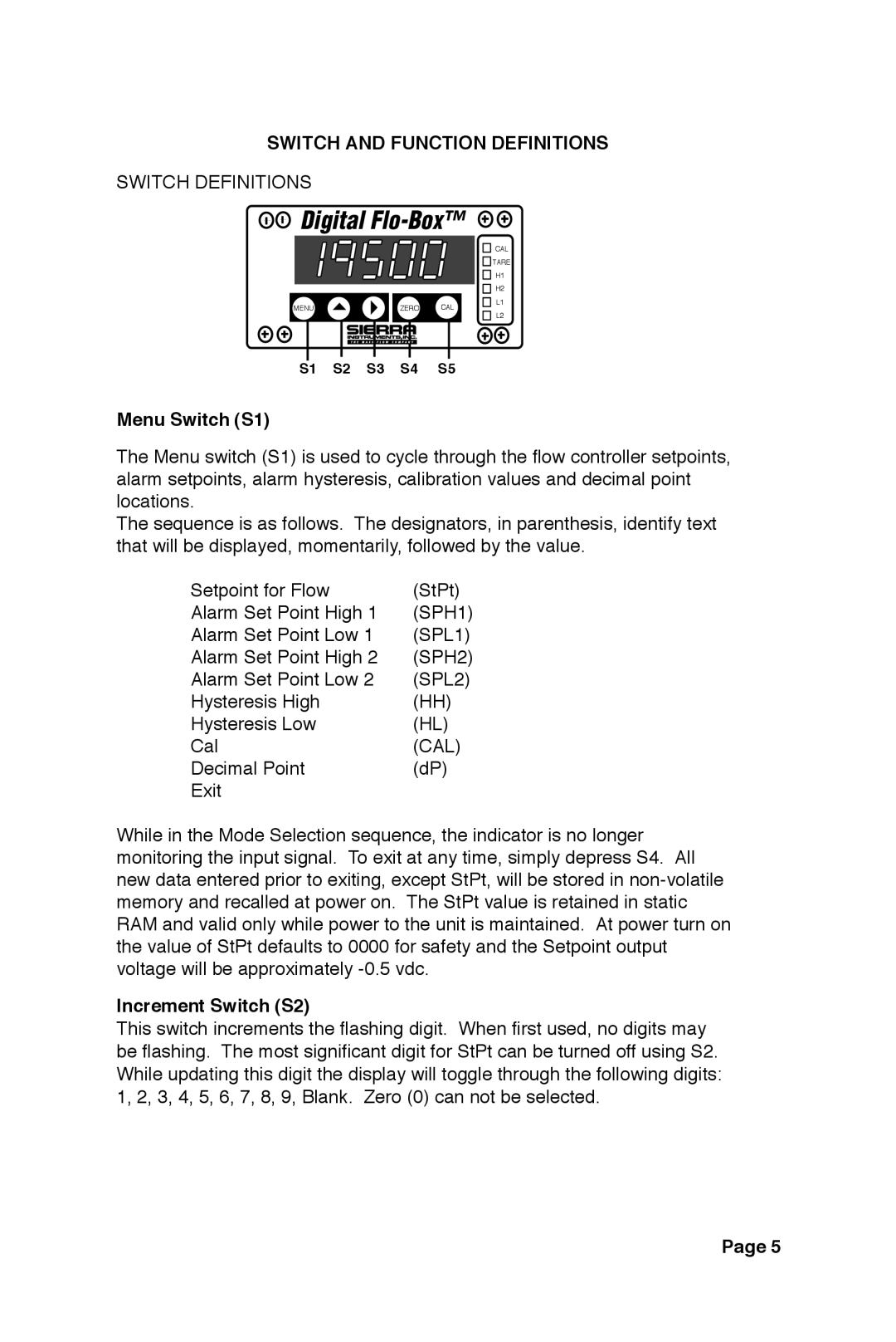
S1 S2 S3 S4 S5
Menu Switch (S1)
The Menu switch (S1) is used to cycle through the flow controller setpoints, alarm setpoints, alarm hysteresis, calibration values and decimal point locations.
The sequence is as follows. The designators, in parenthesis, identify text that will be displayed, momentarily, followed by the value.
Setpoint for Flow | (StPt) |
Alarm Set Point High 1 | (SPH1) |
Alarm Set Point Low 1 | (SPL1) |
Alarm Set Point High 2 | (SPH2) |
Alarm Set Point Low 2 | (SPL2) |
Hysteresis High | (HH) |
Hysteresis Low | (HL) |
Cal | (CAL) |
Decimal Point | (dP) |
Exit |
|
While in the Mode Selection sequence, the indicator is no longer monitoring the input signal. To exit at any time, simply depress S4. All new data entered prior to exiting, except StPt, will be stored in
Increment Switch (S2)
This switch increments the flashing digit. When first used, no digits may be flashing. The most significant digit for StPt can be turned off using S2. While updating this digit the display will toggle through the following digits: 1, 2, 3, 4, 5, 6, 7, 8, 9, Blank. Zero (0) can not be selected.
Page 5