OPERATING INSTRUCTIONS
TURN-ON INSTRUCTIONS
Reference Figures 3 and 4 for proper input and output signal wiring.
1.Apply power to the instrument.
2.Verify the instrument readout blanks momentarily, then displays the value of the input signal. If the display blinks continuously it is because the Model 951 is not receiving a signal. Check wiring.
3.If your Model 951 was calibrated at the factory, youʼre ready to go. If it was not factory calibrated see page 13..
PROGRAM INSTRUCTIONS (Refer to program menu diagram on page 17)
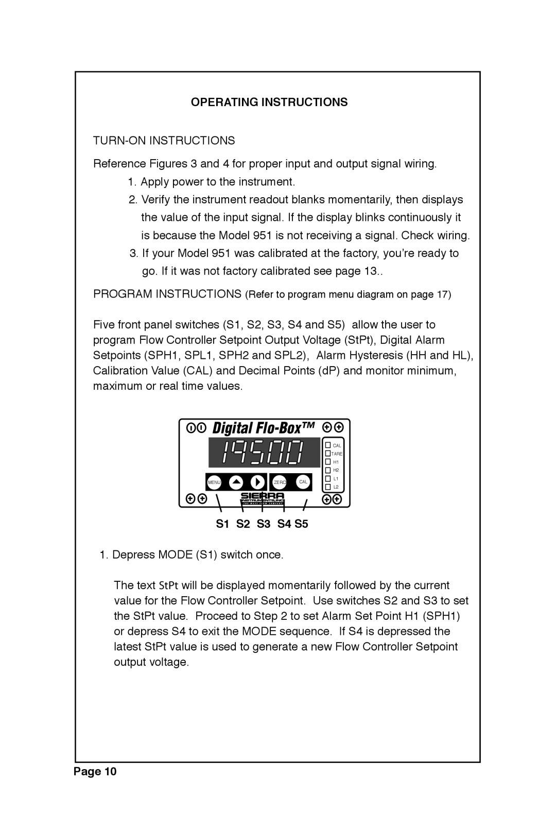
Five front panel switches (S1, S2, S3, S4 and S5) allow the user to program Flow Controller Setpoint Output Voltage (StPt), Digital Alarm Setpoints (SPH1, SPL1, SPH2 and SPL2), Alarm Hysteresis (HH and HL), Calibration Value (CAL) and Decimal Points (dP) and monitor minimum, maximum or real time values.
![]()
![]() ����������������
����������������
|
|
| CAL | |
|
|
| TARE | |
|
|
| H1 | |
|
|
| H2 | |
MENU | ZERO | CAL | L1 | |
L2 | ||||
|
|
|
S1 S2 S3 S4 S5
1. Depress MODE (S1) switch once.
The text ���� will be displayed momentarily followed by the current value for the Flow Controller Setpoint. Use switches S2 and S3 to set the StPt value. Proceed to Step 2 to set Alarm Set Point H1 (SPH1) or depress S4 to exit the MODE sequence. If S4 is depressed the latest StPt value is used to generate a new Flow Controller Setpoint output voltage.
Page 10