MP215 Mobile Modem | Installation, Configuration, and User’s Guide |
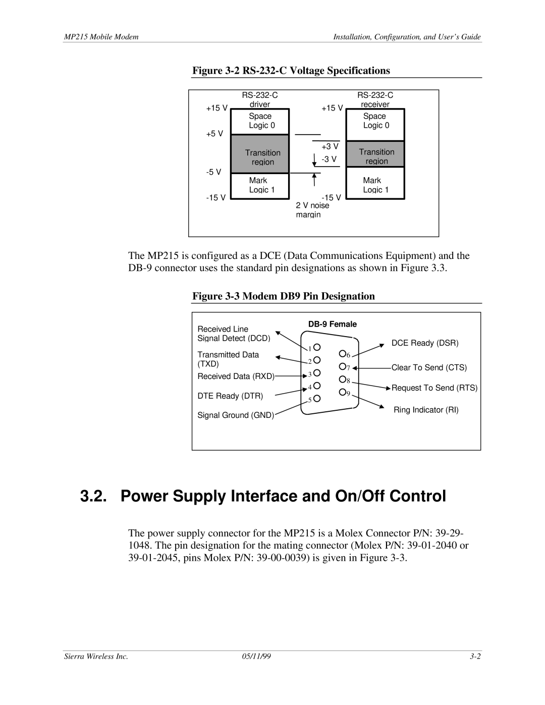
Figure 3-2 RS-232-C Voltage Specifications
+15 V
+5 V
driver
Space
Logic 0
Transition
region
Mark
Logic 1
+15 V
+3 V
2 V noise margin
receiver
Space
Logic 0
Transition
region
Mark
Logic 1
The MP215 is configured as a DCE (Data Communications Equipment) and the
Figure 3-3 Modem DB9 Pin Designation
Received Line |
|
|
|
|
|
| ||
|
|
|
|
|
|
| ||
Signal Detect (DCD) |
| 1 |
|
|
| DCE Ready (DSR) | ||
|
|
|
| |||||
Transmitted Data |
|
|
|
| ||||
|
|
| ||||||
|
|
|
|
| ||||
| 6 |
|
|
|
| |||
(TXD) |
| 2 |
|
|
| Clear To Send (CTS) | ||
|
|
| 7 |
|
|
| ||
|
|
|
|
|
| |||
Received Data (RXD) |
|
|
| 3 |
|
|
|
|
|
|
|
|
|
| |||
|
|
| 8 |
|
|
| Request To Send (RTS) | |
|
|
| 4 |
|
|
| ||
DTE Ready (DTR) |
| 9 |
|
|
|
| ||
Signal Ground (GND) |
| 5 |
|
|
| Ring Indicator (RI) | ||
|
|
| ||||||
|
|
|
|
|
| |||
|
|
|
|
|
|
| ||
|
|
|
|
|
|
|
|
|
3.2. Power Supply Interface and On/Off Control
The power supply connector for the MP215 is a Molex Connector P/N:
1048. The pin designation for the mating connector (Molex P/N:
Sierra Wireless Inc. | 05/11/99 |