MP215 Mobile Modem | Installation, Configuration, and User’s Guide |
NOTE
The naming convention and signal flow is with respect to the modem not the PC (host) side. This means that TXD on the modem side is RXD on the Host Side and vice versa.
The directions of the arrows indicate signal flow into the pin or signal flow out of the pin. For example, the pin labeled TXD has the signal flowing out of the pin and the arrow pointing away from the pin.
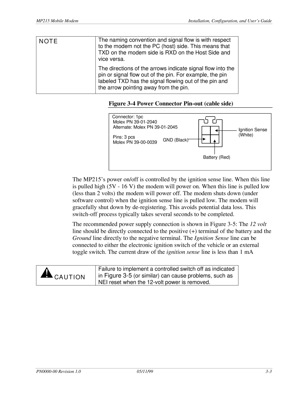
Figure 3-4 Power Connector Pin-out (cable side)
Connector: 1pc
Molex PN
Alternate: Molex PN
Pins: 3 pcs | GND (Black) |
|
Molex PN |
| |
|
|
![]() Ignition Sense (White)
Ignition Sense (White)
Battery (Red)
The MP215’s power on/off is controlled by the ignition sense line. When this line is pulled high (5V - 16 V) the modem will power on. When this line is pulled low (less than 2 volts) the modem will power off. The modem shuts down (under software control) when the ignition sense line is pulled low. The modem will gracefully shut down by
The recommended power supply connection is shown in Figure
![]() CAUTION
CAUTION
Failure to implement a controlled switch off as indicated in Figure
05/11/99 |