Operation
II | I. | I |
/
-
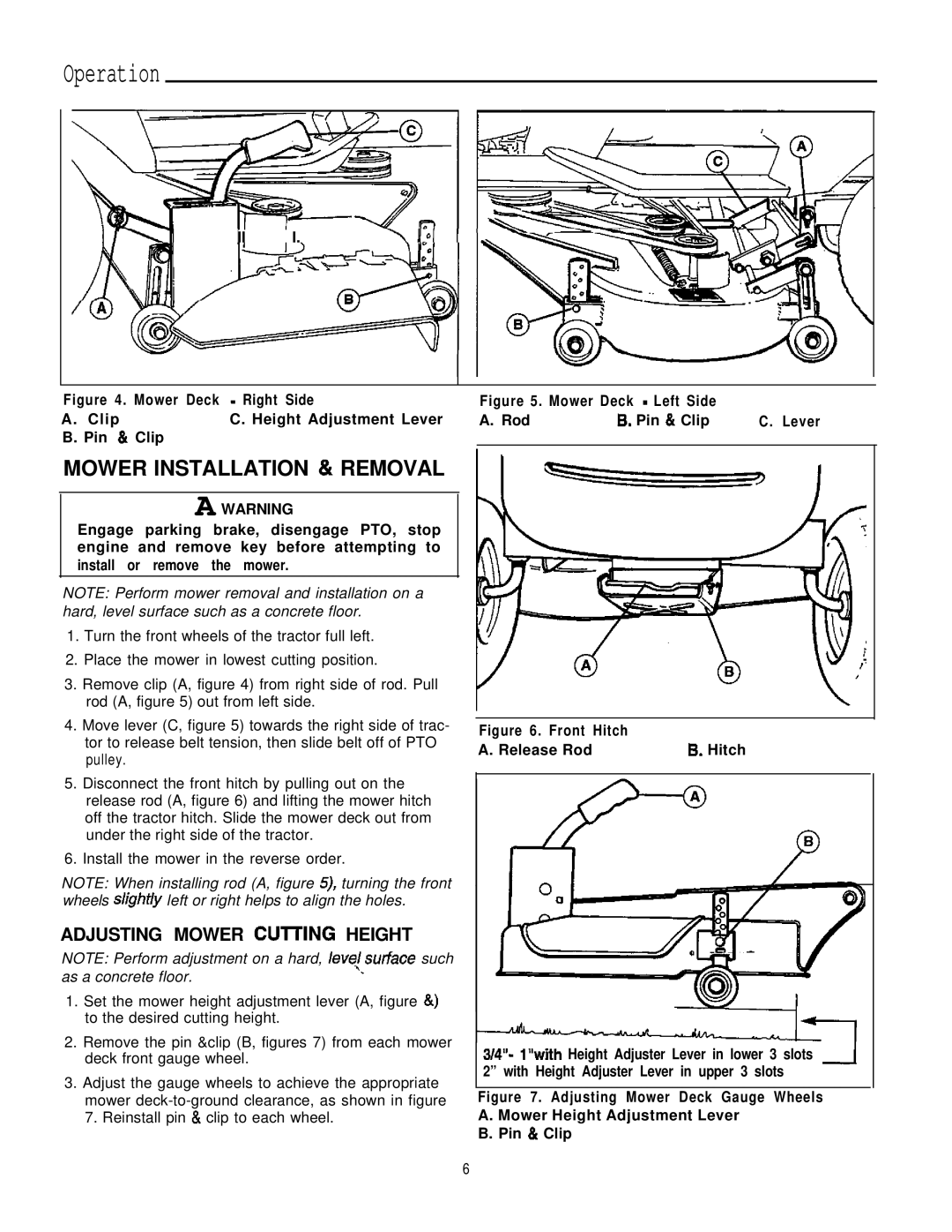
Figure 4 . Mower Deck - Right Side
A . ClipC. Height Adjustment Lever B. Pin 84 Clip
MOWER INSTALLATION & REMOVAL
A WARNING
Engage parking brake, disengage PTO, stop engine and remove key before attempting to install or remove the mower.
NOTE: Perform mower removal and installation on a hard, level surface such as a concrete floor.
1.Turn the front wheels of the tractor full left.
2.Place the mower in lowest cutting position.
3.Remove clip (A, figure 4) from right side of rod. Pull rod (A, figure 5) out from left side.
4.Move lever (C, figure 5) towards the right side of trac- tor to release belt tension, then slide belt off of PTO pulley.
5.Disconnect the front hitch by pulling out on the release rod (A, figure 6) and lifting the mower hitch off the tractor hitch. Slide the mower deck out from under the right side of the tractor.
6.Install the mower in the reverse order.
NOTE: When installing rod (A, figure 5), turning the front wheels slight/y left or right helps to align the holes.
ADJUSTING MOWER CUlTlNG HEIGHT
NOTE: Perform adjustment on a hard, leve,l.surface such as a concrete floor.
1.Set the mower height adjustment lever (A, figure &) to the desired cutting height.
2.Remove the pin &clip (B, figures 7) from each mower deck front gauge wheel.
3.Adjust the gauge wheels to achieve the appropriate mower
Figure 5. Mower Deck - Left Side |
| |
A. Rod | 6. Pin & Clip | C . Lever |
Figure 6. Front Hitch |
|
A. Release Rod | 6. Hitch |
3/4”- 1”with Height Adjuster Lever in lower 3 slots -I 2” with Height Adjuster Lever in upper 3 slots
Figure 7. Adjusting Mower Deck Gauge Wheels A. Mower Height Adjustment Lever
B. Pin & Clip
6
