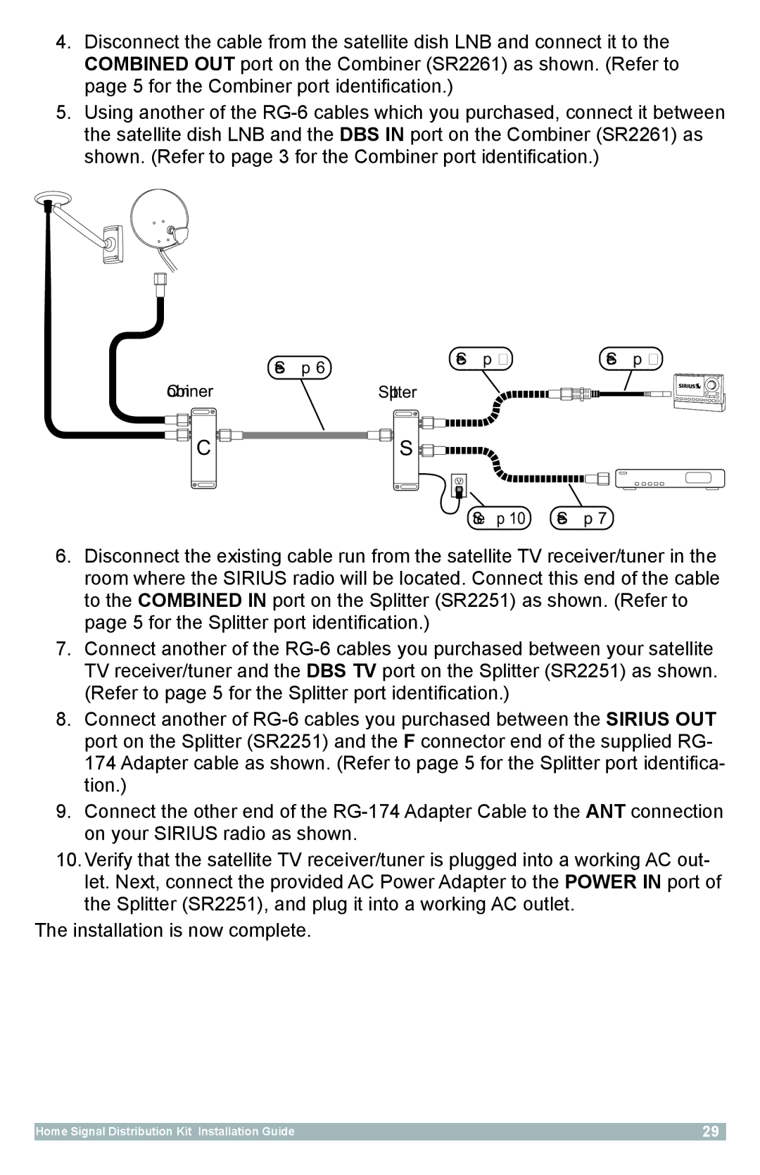
4.Disconnect the cable from the satellite dish LNB and connect it to the
COMBINED OUT port on the Combiner (SR2261) as shown. (Refer to page 5 for the Combiner port identification.)
5.Using another of the
Step 6 | Step 8 | Step 9 |
|
|
CombinerSplitter
![]()
![]() C
C ![]()
![]()
![]() S
S ![]()
Step 10 | Step 7 |
6.Disconnect the existing cable run from the satellite TV receiver/tuner in the room where the SIRIUS radio will be located. Connect this end of the cable to the COMBINED IN port on the Splitter (SR2251) as shown. (Refer to page 5 for the Splitter port identification.)
7.Connect another of the
8.Connect another of
9.Connect the other end of the
10.Verify that the satellite TV receiver/tuner is plugged into a working AC out- let. Next, connect the provided AC Power Adapter to the POWER IN port of the Splitter (SR2251), and plug it into a working AC outlet.
The installation is now complete.
Home Signal Distribution Kit Installation Guide | 29 |
