Combiner and Splitter Port Identification
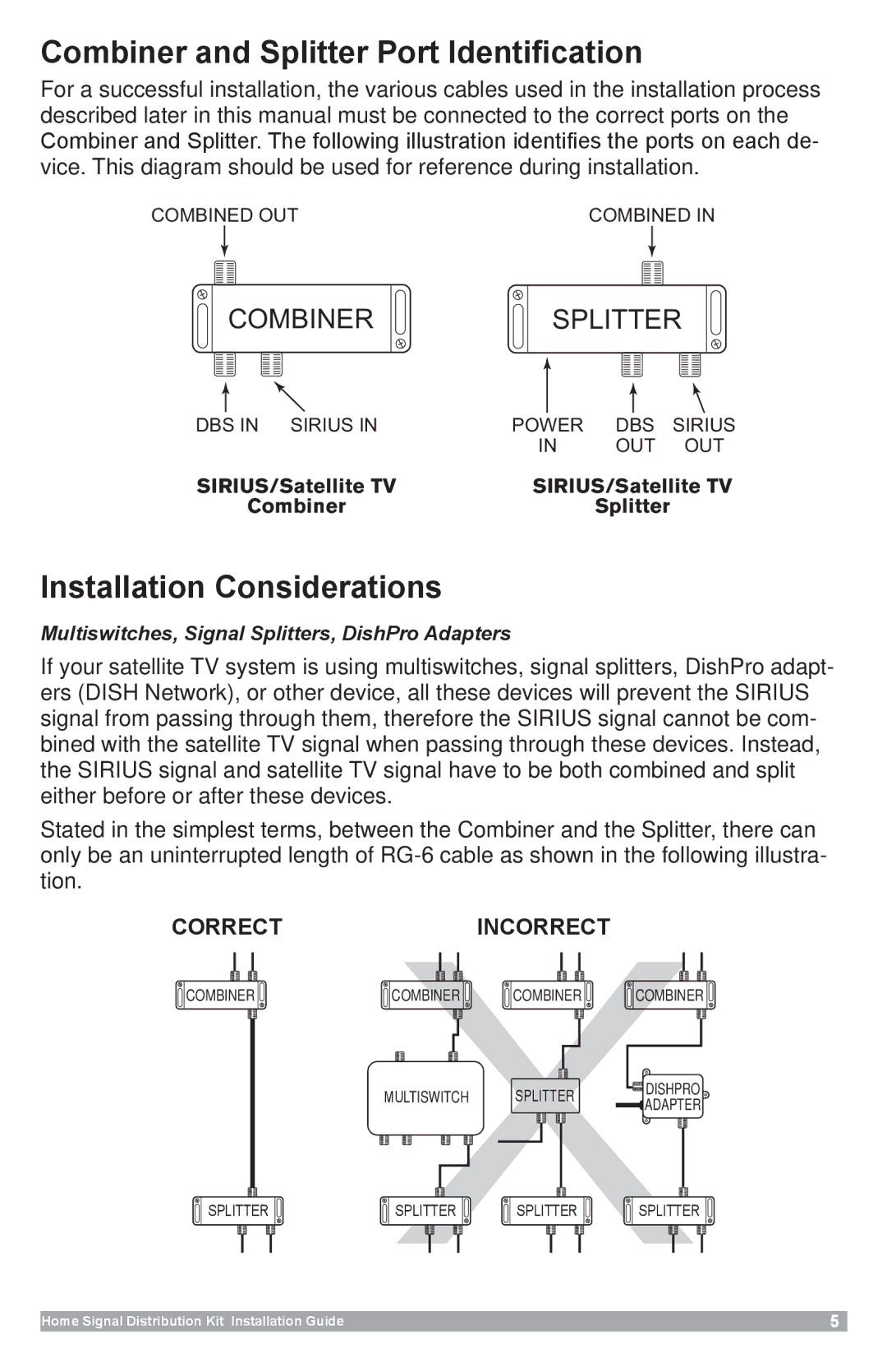
For a successful installation, the various cables used in the installation process described later in this manual must be connected to the correct ports on the Combiner and Splitter. The following illustration identifies the ports on each de- vice. This diagram should be used for reference during installation.
COMBINED OUT | COMBINED IN |
![]()
![]() COMBINER
COMBINER ![]()
![]()
SPLITTER
|
|
|
|
|
|
|
|
|
|
|
|
|
|
DBS IN SIRIUS IN | POWER | DBS | SIRIUS | |||
|
| IN | OUT | OUT | ||
SIRIUS/Satellite TV | SIRIUS/Satellite TV | |||||
| Combiner |
|
| Splitter |
| |
Installation Considerations
Multiswitches, Signal Splitters, DishPro Adapters
If your satellite TV system is using multiswitches, signal splitters, DishPro adapt- ers (DISH Network), or other device, all these devices will prevent the SIRIUS signal from passing through them, therefore the SIRIUS signal cannot be com- bined with the satellite TV signal when passing through these devices. Instead, the SIRIUS signal and satellite TV signal have to be both combined and split either before or after these devices.
Stated in the simplest terms, between the Combiner and the Splitter, there can only be an uninterrupted length of
CoRReCTInCoRReCT
COMBINER | COMBINER | COMBINER | COMBINER |
| MULTISWITCH | SPLITTER | DISHPRO |
| ADAPTER | ||
|
|
| |
SPLITTER | SPLITTER | SPLITTER | SPLITTER |