Safety
! | WARNING | “READ ALL INSTRUCTIONS” — Failure to follow the SAFETY RULES identified by BULLET (l) symbol listed | |
BELOW and other safety precautions, may result in serious personal injury. | |||
|
|
Double Insulated Tools
Double insulation ![]()
![]()
![]() is a design concept used in electric power tools which eliminates the need for the three wire grounded power cord and grounded power supply system. It is a recognized and approved system by Underwriter’s Laboratories, CSA and Federal OSHA authorities.
is a design concept used in electric power tools which eliminates the need for the three wire grounded power cord and grounded power supply system. It is a recognized and approved system by Underwriter’s Laboratories, CSA and Federal OSHA authorities.
•Servicing of a tool with double insulation requires care and knowledge of the system and should be performed only by a qualified service technician.
•WHEN SERVICING, USE ONLY IDENTICAL REPLACEMENT PARTS.
•POLARIZED PLUGS. If your tool is equipped with a polarized plug (one blade is wider than the other), this plug will fit in a polarized outlet only one way. If the plug does not fit fully in the outlet, reverse the plug. If it still does not fit, contact a qualified electrician to install the proper outlet. Do not change the plug in any way.
“SAVE THESE INSTRUCTIONS”
Extension Cords
•Replace damaged cords immediately. Use of damaged cords can shock, burn or electrocute.
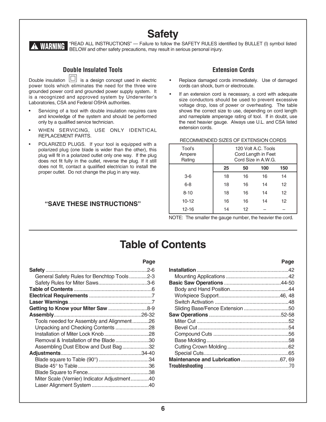
•If an extension cord is necessary, a cord with adequate size conductors should be used to prevent excessive voltage drop, loss of power or overheating. The table shows the correct size to use, depending on cord length and nameplate amperage rating of tool. If in doubt, use the next heavier gauge. Always use U.L. and CSA listed extension cords.
RECOMMENDED SIZES OF EXTENSION CORDS
Tool’s |
| 120 Volt A.C. Tools |
| |
Ampere |
| Cord Length in Feet |
| |
Rating |
| Cord Size in A.W.G. |
| |
|
|
|
|
|
| 25 | 50 | 100 | 150 |
|
|
|
|
|
18 | 16 | 16 | 14 | |
18 | 16 | 14 | 12 | |
18 | 16 | 14 | 12 | |
16 | 16 | 14 | 12 | |
14 | 12 | – | – | |
|
|
|
|
|
NOTE: The smaller the gauge number, the heavier the cord.
Table of Contents
| Page |
| Page |
Safety | Installation | 42 | |
General Safety Rules for Benchtop Tools | Mounting Applications | 42 | |
Safety Rules for Miter Saws | Basic Saw Operations | ||
Table of Contents | 6 | Body and Hand Position | 44 |
Electrical Requirements | 7 | Workpiece Support | 46, 48 |
Laser Warnings | 7 | Switch Activation | 48 |
Getting to Know your Miter Saw | Sliding Base/Fence Extension | 50 | |
Assembly | Saw Operations | ||
Tools needed for Assembly and Alignment | 26 | Miter Cut | 52 |
Unpacking and Checking Contents | 28 | Bevel Cut | 54 |
Installation of Miter Lock Knob | 28 | Compound Cuts | 56 |
Removal & Installation of the Blade | 30 | Base Molding | 58 |
Assembling Dust Elbow and Dust Bag | 32 | Cutting Crown Molding | 62 |
Adjustments | Special Cuts | 65 | |
Blade square to Table (90°) | 34 | Maintenance and Lubrication | 67, 69 |
Blade 45° to Table | 36 | Troubleshooting | 70 |
Blade Square to Fence | 38 |
|
|
Miter Scale (Vernier) Indicator Adjustment | 40 |
|
|
Laser Alignment System | 40 |
|
|
6