OPERATION
When the sensor is running low in battery, the sensor will send a wireless low battery signal to the control panel. The zone LED representing that sensor will be on steadily, indicating sensor(s) in that zone is in trouble condition. Control Panel will also have an announcement to advise the user the trouble condition is low battery, such as “zone X sensor Y low battery”, where X and Y represent the zone and sensor number. Please replace the battery of that sensor.
Keychain Remote (Sold separately)
The battery of the keychain remote (Alkaline, Type 23A, 12V) needs to be replaced when either one of the followings occurs:
1.The LED on the keychain doesn’t flash or on when a key is pressed; or
2.The operating range starts to decrease.
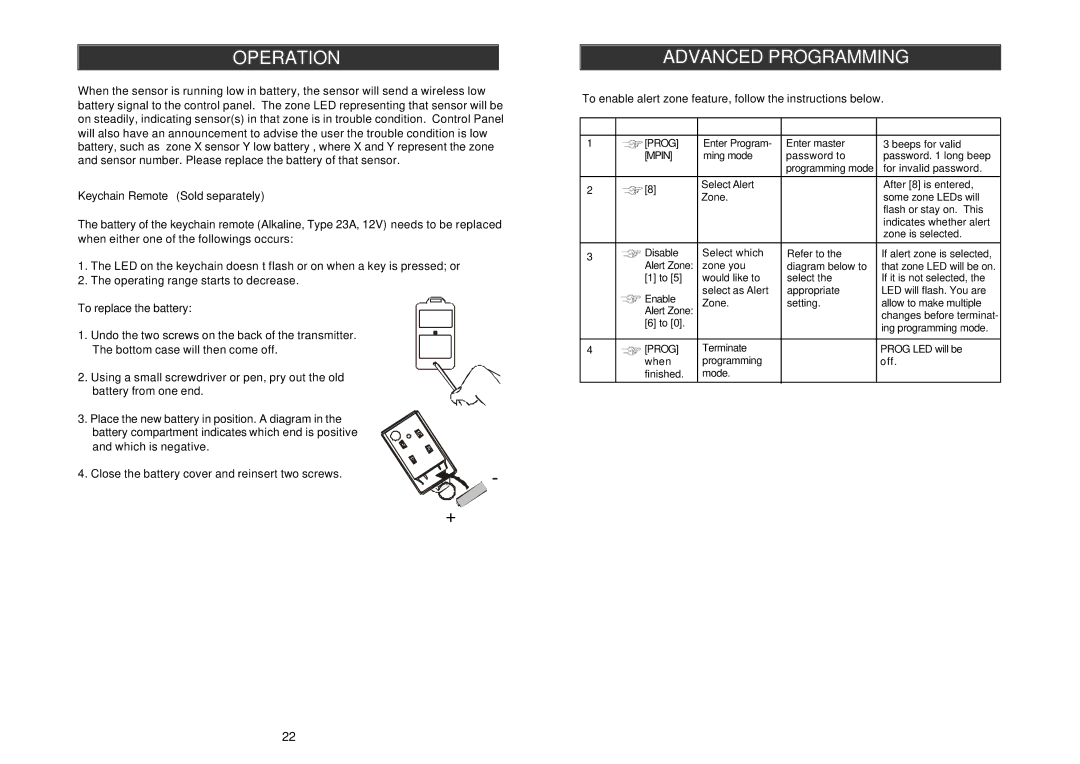
To replace the battery:
1. Undo the two screws on the back of the transmitter. The bottom case will then come off.
2. Using a small screwdriver or pen, pry out the old battery from one end.
ADVANCED PROGRAMMING
To enable alert zone feature, follow the instructions below.
Step | Keys | Function | Description | Note |
1 | [PROG] | Enter Program- | Enter master | 3 beeps for valid |
| [MPIN] | ming mode | password to | password. 1 long beep |
|
|
| programming mode | for invalid password. |
|
|
|
|
|
2 | [8] | Select Alert |
| After [8] is entered, |
Zone. |
| some zone LEDs will | ||
|
|
| ||
|
|
|
| flash or stay on. This |
|
|
|
| indicates whether alert |
|
|
|
| zone is selected. |
|
|
|
|
|
3 | Disable | Select which | Refer to the | If alert zone is selected, |
| Alert Zone: | zone you | diagram below to | that zone LED will be on. |
| [1] to [5] | would like to | select the | If it is not selected, the |
| Enable | select as Alert | appropriate | LED will flash. You are |
| Zone. | setting. | allow to make multiple | |
| Alert Zone: | |||
| [6] to [0]. |
|
| changes before terminat- |
|
|
| ing programming mode. | |
|
|
|
| |
|
|
|
|
|
4 | [PROG] | Terminate |
| PROG LED will be |
| when | programming |
| off. |
| finished. | mode. |
|
|
|
|
|
|
|
3. Place the new battery in position. A diagram in the battery compartment indicates which end is positive and which is negative.
4. Close the battery cover and reinsert two screws. | - |
|
+
| DISABLE | ENABLE |
|
| ® | ||
|
|
|
|
|
| ||
| ALERT ZONE | ALERT ZONE |
|
|
|
|
|
Zone 1 | Button [1] | Button [6] |
|
|
|
|
|
|
|
|
|
|
|
|
|
Zone 2 | Button [2] | Button [7] |
|
|
|
|
|
|
|
|
|
|
|
|
|
Zone 3 | Button [3] | Button [8] |
|
|
|
|
|
|
|
|
|
|
|
|
|
Zone 4 | Button [4] | Button [9] |
|
|
|
|
|
|
|
|
|
|
|
|
|
Zone 5 | Button [5] | Button [0] |
|
|
|
|
|
|
|
|
|
|
|
|
|
|
|
|
|
|
|
|
|
This row :
Buttons to
Disable Alert Zone
Zone LED : Flash
This row :
Buttons to
Enable Alert Zone
Zone LED : ON
