Sentry | 11 |
a.Boiler (burner) is overfiring. CAUTION! National Fuel Gas Code ANSI
b.Poor higher* heating value of gas is causing the actu- al input to be substantially lower than the rating plate indication.
*“Higher heating value” of gas is commonly known as a “heating value.”
GAS RATE TABLE
The gas metered in 3 minutes to obtain rated input for each boiler model, using 1000 Btu/cu. ft. gas, is tabulated in gas rate table.
|
|
|
|
|
|
|
| Boiler rated input in |
| Cubic Feet | |
|
|
| Gas Consumption | ||
|
| cu. ft./hr. of 1000 Btu/cu. ft. |
| ||
|
|
| 1000 Btu/cu. ft. gas, in 3 | ||
|
| Natural Gas |
| ||
|
|
| minutes, at rated input | ||
|
|
|
| ||
|
|
|
|
|
|
34 |
| 1.70 |
| ||
|
| 60 |
| 3.00 |
|
|
| 90 |
| 4.50 |
|
|
| 120 |
| 6.00 |
|
|
| 150 |
| 7.50 |
|
|
| 180 |
| 9.00 |
|
|
| 210 |
| 10.50 |
|
|
|
|
|
|
|
|
|
|
|
|
|
B. Main Burners
1.Fire the boiler continuously for at least 15 minutes, to reach burner operating temperature.
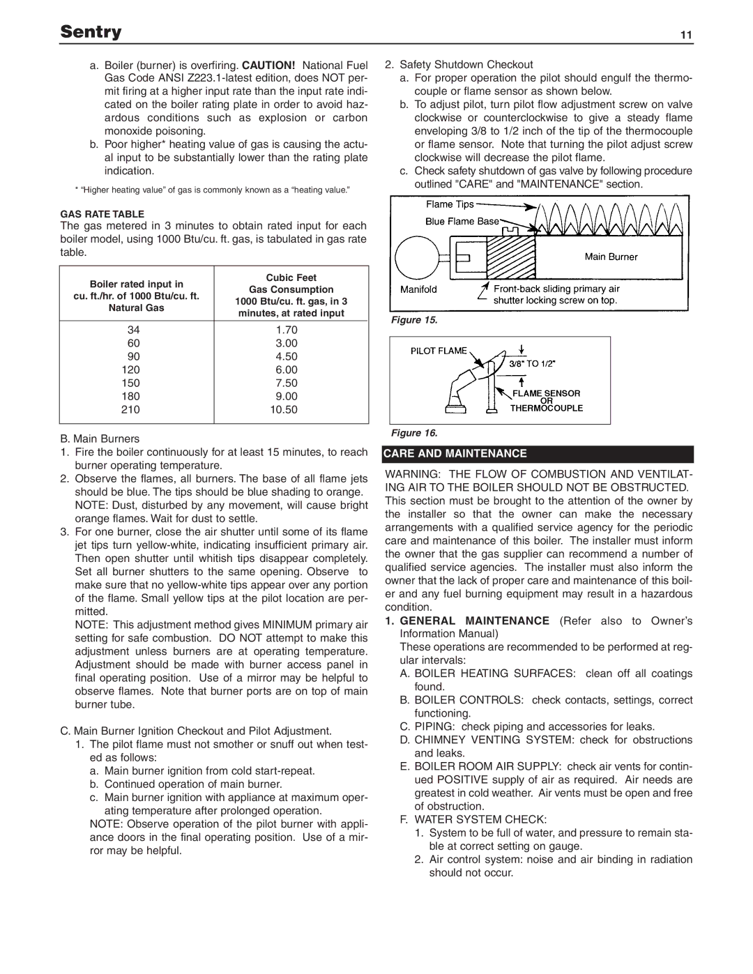
2.Observe the flames, all burners. The base of all flame jets should be blue. The tips should be blue shading to orange. NOTE: Dust, disturbed by any movement, will cause bright orange flames. Wait for dust to settle.
3.For one burner, close the air shutter until some of its flame jet tips turn
NOTE: This adjustment method gives MINIMUM primary air setting for safe combustion. DO NOT attempt to make this adjustment unless burners are at operating temperature. Adjustment should be made with burner access panel in final operating position. Use of a mirror may be helpful to observe flames. Note that burner ports are on top of main burner tube.
C. Main Burner Ignition Checkout and Pilot Adjustment.
1.The pilot flame must not smother or snuff out when test- ed as follows:
a.Main burner ignition from cold
b.Continued operation of main burner.
c.Main burner ignition with appliance at maximum oper-
ating temperature after prolonged operation.
NOTE: Observe operation of the pilot burner with appli- ance doors in the final operating position. Use of a mir- ror may be helpful.
2.Safety Shutdown Checkout
a.For proper operation the pilot should engulf the thermo- couple or flame sensor as shown below.
b.To adjust pilot, turn pilot flow adjustment screw on valve clockwise or counterclockwise to give a steady flame enveloping 3/8 to 1/2 inch of the tip of the thermocouple or flame sensor. Note that turning the pilot adjust screw clockwise will decrease the pilot flame.
c.Check safety shutdown of gas valve by following procedure outlined "CARE" and "MAINTENANCE" section.
Figure 15.
Figure 16.
CARE AND MAINTENANCE
WARNING: THE FLOW OF COMBUSTION AND VENTILAT- ING AIR TO THE BOILER SHOULD NOT BE OBSTRUCTED. This section must be brought to the attention of the owner by the installer so that the owner can make the necessary arrangements with a qualified service agency for the periodic care and maintenance of this boiler. The installer must inform the owner that the gas supplier can recommend a number of qualified service agencies. The installer must also inform the owner that the lack of proper care and maintenance of this boil- er and any fuel burning equipment may result in a hazardous condition.
1.GENERAL MAINTENANCE (Refer also to Owner’s Information Manual)
These operations are recommended to be performed at reg- ular intervals:
A.BOILER HEATING SURFACES: clean off all coatings found.
B.BOILER CONTROLS: check contacts, settings, correct functioning.
C.PIPING: check piping and accessories for leaks.
D.CHIMNEY VENTING SYSTEM: check for obstructions and leaks.
E.BOILER ROOM AIR SUPPLY: check air vents for contin- ued POSITIVE supply of air as required. Air needs are greatest in cold weather. Air vents must be open and free of obstruction.
F.WATER SYSTEM CHECK:
1.System to be full of water, and pressure to remain sta- ble at correct setting on gauge.
2.Air control system: noise and air binding in radiation should not occur.