5.Locate the
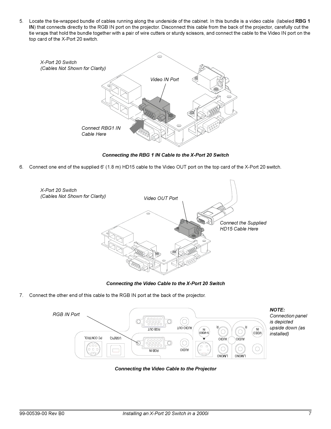
(Cables Not Shown for Clarity)
Video IN Port
Connect RBG1 IN
Cable Here
Connecting the RBG 1 IN Cable to the X-Port 20 Switch
6.Connect one end of the supplied 6' (1.8 m) HD15 cable to the Video OUT port on the top card of the
| |
(Cables Not Shown for Clarity) | Video OUT Port |
|
Connect the Supplied
HD15 Cable Here
Connecting the Video Cable to the X-Port 20 Switch
7.Connect the other end of this cable to the RGB IN port at the back of the projector.
RGB IN Port
| OUT RGB | OUT AUDIO | IN | R |
|
| |||
|
|
| ||
|
|
|
| |
CONTROL PC | USB(PC) |
|
| AUDIO |
|
|
|
| |
| IN RGB | AUDIO |
|
|
|
|
|
| L/MONO |
Connecting the Video Cable to the Projector
R | IN |
| |
| VIDEO |
AUDIO
L/MONO
NOTE: Connection panel is depicted upside down (as installed)
| Installing an | 7 |