GS110 DIRECT VENT BOILER INSTALLATION AND OPERATION INSTRUCTIONS

Page 11

Horizontal vent systems shall terminate at least 4 feet (1.3 m) below, 4 feet (1.3 m) horizontally from or 1 foot (0.23 m) above any door, window or gravity air inlet into any building. It must not terminate less than 4 feet (1.3

m)horizontally from, and in no case above or below, unless a 4 feet (1.3 m) horizontal distance is maintained, from electric meters, gas meters, regulators and relief equipment and not less than 7 feet (2.3 m) from any adjacent public walkway. The bottom of the vent terminal(s) shall be located at least 5 feet (1.5 m) above the air intake terminal(s). Avoid terminal locations likely to be affected by winds, snowdrifts, people and pets.

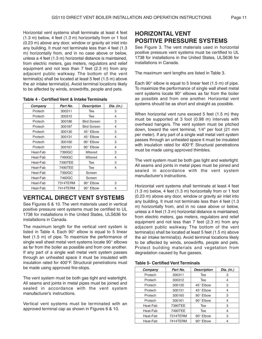
Table 4 - Certified Vent & Intake Terminals

Company

Part No.

Description

Dia. (in.)

Protech

300311

Tee

3

Protech

300312

Tee

4

Protech

300186

Bird Screen

3

Protech

300187

Bird Screen

4

Protech

300130

45° Elbow

3

Protech

300131

45° Elbow

4

Protech

300160

90° Elbow

3

Protech

300161

90° Elbow

4

Heat-Fab

7390GC

Mitered

3

Heat-Fab

7490GC

Mitered

4

Heat-Fab

7390TEE

Tee

3

Heat-Fab

7490TEE

Tee

4

Heat-Fab

7392GC

Screen


Heat-Fab

7492GC

Screen


Heat-Fab

7314TERM

90° Elbow

3

Heat-Fab

7414TERM

90° Elbow

4

VERTICAL DIRECT VENT SYSTEMS

See Figures 6 & 10. The vent materials used in vertical positive pressure vent systems must be certified to UL 1738 for installations in the United States, ULS636 for installations in Canada.

The maximum length for the vertical vent system is listed in Table 4. Each 90° elbow is equal to 5 linear feet (1.5 m) of pipe. To maximize the performance of single wall sheet metal vent systems locate 90° elbows as far from the boiler as possible and from one another. If any part of a single wall metal vent system passes through an unheated space it must be insulated with insulation rated for 400°F. Structural penetrations must be made using approved fire-stops.

The vent system must be both gas tight and watertight. All seams and joints in metal pipes must be joined and sealed in accordance with the vent system manufacturer’s instructions.

Vertical vent systems must be terminated with an approved terminal cap as shown in Figures 6 & 10.

HORIZONTAL VENT

POSITIVE PRESSURE SYSTEMS

See Figure 3. The vent materials used in horizontal positive pressure vent systems must be certified to UL 1738 for installations in the United States, ULS636 for installations in Canada.

The maximum vent lengths are listed in Table 3.

Each 90° elbow is equal to 5 linear feet (1.5 m) of pipe. To maximize the performance of single wall sheet metal vent systems locate 90° elbows as far from the boiler as possible and from one another. Horizontal vent systems should be as short and straight as possible.

When horizontal vent runs exceed 5 feet (1.5 m) they must be supported at 3 foot (0.98 m) intervals with overhead hangers. The vent system must be pitched down, toward the vent terminal, 1/4" per foot (21 mm per meter). If any part of a single wall metal vent system passes through an unheated space it must be insulated with insulation rated for 400°F. Structural penetrations must be made using approved thimbles.

The vent system must be both gas tight and watertight. All seams and joints in metal pipes must be joined and sealed in accordance with the vent system manufacturer's instructions.

Horizontal vent systems shall terminate at least 4 feet (1.3 m) below, 4 feet (1.3 m) horizontally from or 1 foot (0.23 m) above any door, window or gravity air inlet into any building. It must not terminate less than 4 feet (1.3

m)horizontally from, and in no case above or below, unless a 4 feet (1.3 m) horizontal distance is maintained, from electric meters, gas meters, regulators and relief equipment and not less than 7 feet (2.3 m) from any adjacent public walkway. The bottom of the vent terminal(s) shall be located at least 5 feet (1.5 m) above the air intake terminal(s). Avoid terminal locations likely to be affected by winds, snowdrifts, people and pets. Protect building materials and vegetation from degradation caused by flue gasses.

Table 5- Certified Vent Terminals

Company

Part No.

Description

Dia. (in.)

Protech

300311

Tee

3

Protech

300312

Tee

4

Protech

300130

45° Elbow

3

Protech

300131

45° Elbow

4

Protech

300160

90° Elbow

3

Protech

300161

90° Elbow

4

Heat-Fab

7390TEE

Tee

3

Heat-Fab

7490TEE

Tee

4

Heat-Fab

7314TERM

90° Elbow

3

Heat-Fab

7414TERM

90° Elbow

4

Page 11
Image 11
Smith Cast Iron Boilers GS110W operation manual Vertical Direct Vent Systems, Horizontal Vent Positive Pressure Systems

GS110W specifications

The Smith Cast Iron Boilers GS110W stands as a premier choice for those seeking efficiency and reliability in heating systems. Known for their robust construction and advanced engineering, Smith Boilers are designed to meet the needs of both residential and commercial applications. The GS110W model showcases an impressive blend of performance and durability, making it a favorite among HVAC professionals and end users alike.

One of the main features of the GS110W is its cast iron construction. Cast iron is celebrated for its ability to retain heat, allowing the boiler to operate efficiently while providing consistent warmth over extended periods. This material also contributes to the boiler's longevity, allowing it to withstand the rigors of heating without significant wear and tear. The GS110W is designed to last, making it a wise investment for any heating needs.

The GS110W boasts an output capacity of 110,000 BTU/hour, making it suitable for a variety of heating applications. This output enables it to efficiently heat large spaces, whether in a multi-story building or a spacious home. The boiler’s efficiency rating is further enhanced by its ability to use multi-fuel options. It can efficiently burn oil or gas, providing flexibility depending on the availability and cost of fuel.

In terms of technology, the GS110W incorporates advanced boiler design that includes a submerged combustion chamber. This engineering feature allows for superior heat transfer while minimizing heat loss, ensuring that the maximum amount of energy is utilized for heating. Additionally, the boiler features a low water cutoff to enhance safety, preventing potential overheating and system failures.

Reliability is further ensured through the GS110W’s built-in controls and adjustments. The boiler is equipped with a digital aquastat that allows for precise temperature management, ensuring optimal performance. This user-friendly feature makes it easier for homeowners and technicians to monitor system conditions and make necessary adjustments for peak efficiency.

Another noteworthy characteristic of the Smith Cast Iron Boilers GS110W is its low emissions output. As environmental considerations become increasingly important, the GS110W is designed to minimize its environmental impact while still delivering powerful heating capabilities.

In conclusion, the Smith Cast Iron Boilers GS110W offers an outstanding combination of durability, efficiency, and advanced technology. Its robust cast iron construction, multi-fuel capability, and innovative design features make it a top choice for anyone looking to enhance their heating system. For those in search of reliable and efficient heating solutions, the GS110W stands out as a formidable contender.