Initial Setup & Assembly
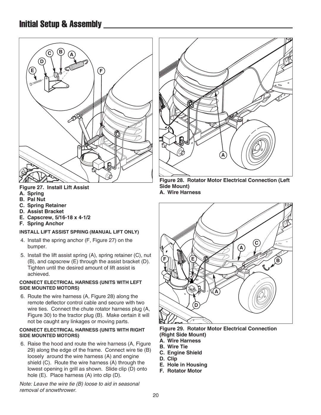
C | B | A |
| ||
D |
|
|
E |
| F |
Figure 27. Install Lift Assist
A.Spring
B.Pal Nut
C.Spring Retainer
D.Assist Bracket
E.Capscrew, 5/16-18 x 4-1/2
F.Spring Anchor
INSTALL LIFT ASSIST SPRING (MANUAL LIFT ONLY)
4.Install the spring anchor (F, Figure 27) on the bumper.
5.Install the lift assist spring (A), spring retainer (C), nut (B), and capscrew (E) through the assist bracket (D). Tighten until the desired amount of lift assist is achieved.
CONNECT ELECTRICAL HARNESS (UNITS WITH LEFT SIDE MOUNTED MOTORS)
6.Route the wire harness (A, Figure 28) along the remote deflector control cable and secure with two wire ties. Connect the chute rotator harness plug (A, Figure 30) to the tractor plug (B). Make certain it will not be caught any linkages or moving parts.
CONNECT ELECTRICAL HARNESS (UNITS WITH RIGHT SIDE MOUNTED MOTORS)
6.Raise the hood and route the wire harness (A, Figure 29) along the edge of the frame. Connect wire tie (B) loosely around the wire harness (A) and engine shield (C). Route the wire harness (A) through the lowest opening in grill as shown. Slide clip (D) onto hole (E). Place harness (A) into clip (D).
Note: Leave the wire tie (B) loose to aid in seasonal removal of snowthrower.
A |
Figure 28. Rotator Motor Electrical Connection (Left
Side Mount)
A. Wire Harness
|
| C |
|
| A |
F | E | B |
|
| |
|
| A |
| D |
|
Figure 29. Rotator Motor Electrical Connection (Right Side Mount)
A.Wire Harness
B.Wire Tie
C.Engine Shield
D.Clip
E.Hole in Housing
F.Rotator Motor
20