Initial Setup & Assembly
Snowthrower
& DozerE
Applications
A
F B C D
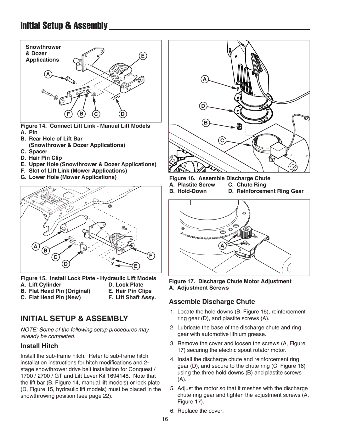
Figure 14. Connect Lift Link - Manual Lift Models
A.Pin
B.Rear Hole of Lift Bar
(Snowthrower & Dozer Applications)
C.Spacer
D.Hair Pin Clip
E.Upper Hole (Snowthrower & Dozer Applications)
F.Slot of Lift Link (Mower Applications)
G.Lower Hole (Mower Applications)
A |
|
|
B |
| F |
C |
| |
| D | E |
|
|
Figure 15. Install Lock Plate - Hydraulic Lift Models
A. Lift Cylinder | D. Lock Plate |
B. Flat Head Pin (Original) | E. Hair Pin Clips |
C. Flat Head Pin (New) | F. Lift Shaft Assy. |
INITIAL SETUP & ASSEMBLY
NOTE: Some of the following setup procedures may already be completed.
Install Hitch
Install the
A |
|
D |
|
B |
|
| C |
Figure 16. Assemble Discharge Chute | |
A. Plastite Screw | C. Chute Ring |
B. | D. Reinforcement Ring Gear |
| A |
Figure 17. Discharge Chute Motor Adjustment A. Adjustment Screws
Assemble Discharge Chute
1.Locate the hold downs (B, Figure 16), reinforcement ring gear (D), and plastite screws (A).
2.Lubricate the base of the discharge chute and ring gear with automotive lithium grease.
3.Remove the cover and loosen the screws (A, Figure 17) securing the electric spout rotator motor.
4.Install the discharge chute and reinforcement ring gear (D), and secure to the chute ring (C, Figure 16) using the three hold downs (B) and plastite screws
(A).
5.Adjust the motor so that it meshes with the discharge chute ring gear and tighten the adjustment screws (A, Figure 17).
6.Replace the cover.
16