Initial Setup & Assembly
A | B |
|
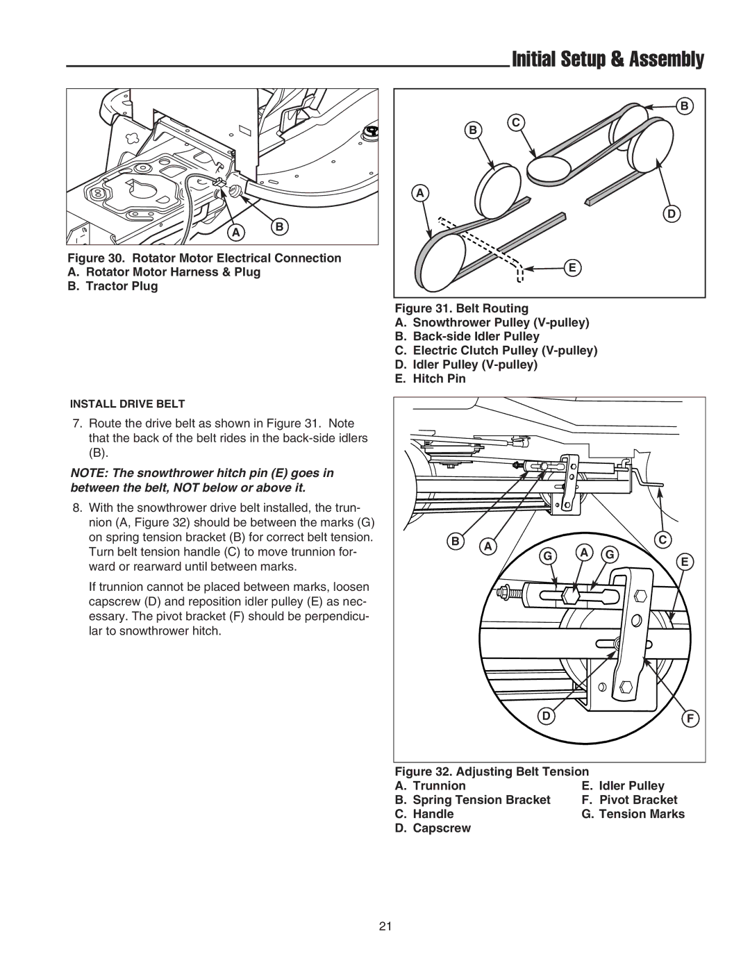
Figure 30. Rotator Motor Electrical Connection
A.Rotator Motor Harness & Plug
B.Tractor Plug
B |
C |
B |
A |
D |
E |
Figure 31. Belt Routing
A.Snowthrower Pulley (V-pulley)
B.Back-side Idler Pulley
C.Electric Clutch Pulley (V-pulley)
D.Idler Pulley (V-pulley)
E.Hitch Pin
INSTALL DRIVE BELT
7.Route the drive belt as shown in Figure 31. Note that the back of the belt rides in the
(B).
NOTE: The snowthrower hitch pin (E) goes in between the belt, NOT below or above it.
8.With the snowthrower drive belt installed, the trun- nion (A, Figure 32) should be between the marks (G) on spring tension bracket (B) for correct belt tension. Turn belt tension handle (C) to move trunnion for- ward or rearward until between marks.
If trunnion cannot be placed between marks, loosen capscrew (D) and reposition idler pulley (E) as nec- essary. The pivot bracket (F) should be perpendicu- lar to snowthrower hitch.
B | A | A | G | C |
| G | E | ||
|
|
|
| |
| D |
|
| F |
Figure 32. Adjusting Belt Tension
A. Trunnion | E. Idler Pulley |
B. Spring Tension Bracket | F. Pivot Bracket |
C. Handle | G. Tension Marks |
D. Capscrew |
|
21