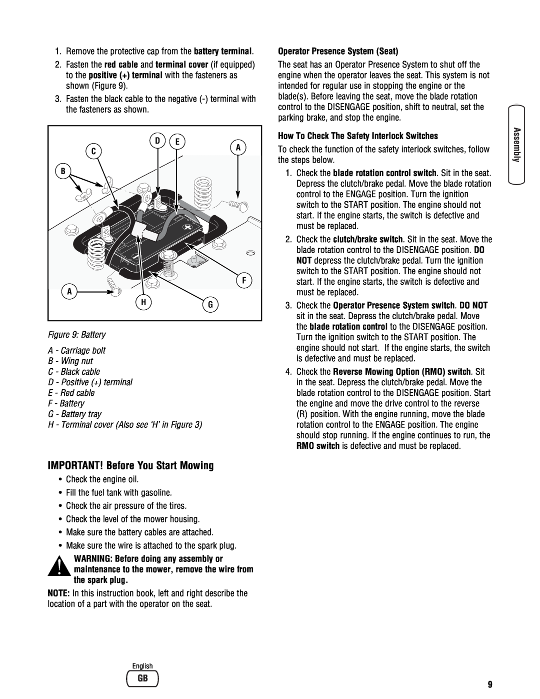
1.Remove the protective cap from the battery terminal.
2.Fasten the red cable and terminal cover (if equipped) to the positive (+) terminal with the fasteners as shown (Figure 9).
3.Fasten the black cable to the negative
D | E |
C | A |
| |
B |
|
| F |
A |
|
H | G |
Figure 9: Battery
A - Carriage bolt
B - Wing nut
C - Black cable
D - Positive (+) terminal
E - Red cable
F - Battery
G - Battery tray
H - Terminal cover (Also see ‘H’ in Figure 3)
IMPORTANT! Before You Start Mowing
•Check the engine oil.
•Fill the fuel tank with gasoline.
•Check the air pressure of the tires.
•Check the level of the mower housing.
•Make sure the battery cables are attached.
•Make sure the wire is attached to the spark plug.
WARNING: Before doing any assembly or maintenance to the mower, remove the wire from the spark plug.
NOTE: In this instruction book, left and right describe the location of a part with the operator on the seat.
Operator Presence System (Seat)
The seat has an Operator Presence System to shut off the engine when the operator leaves the seat. This system is not intended for regular use in stopping the engine or the blade(s). Before leaving the seat, move the blade rotation control to the DISENGAGE position, shift to neutral, set the parking brake, and stop the engine.
How To Check The Safety Interlock Switches
To check the function of the safety interlock switches, follow the steps below.
1.Check the blade rotation control switch. Sit in the seat. Depress the clutch/brake pedal. Move the blade rotation control to the ENGAGE position. Turn the ignition switch to the START position. The engine should not start. If the engine starts, the switch is defective and must be replaced.
2.Check the clutch/brake switch. Sit in the seat. Move the blade rotation control to the DISENGAGE position. DO NOT depress the clutch/brake pedal. Turn the ignition switch to the START position. The engine should not start. If the engine starts, the switch is defective and must be replaced.
3.Check the Operator Presence System switch. DO NOT sit in the seat. Depress the clutch/brake pedal. Move the blade rotation control to the DISENGAGE position. Turn the ignition switch to the START position. The engine should not start. If the engine starts, the switch is defective and must be replaced.
4.Check the Reverse Mowing Option (RMO) switch. Sit in the seat. Depress the clutch/brake pedal. Move the blade rotation control to the DISENGAGE position. Start the engine and move the drive control to the reverse
(R) position. With the engine running, move the blade rotation control to the ENGAGE position. The engine should stop running. If the engine continues to run, the RMO switch is defective and must be replaced.
English
9