How to Check and Adjust the PTO Clutch (46 & 52” Models)
Check the PTO clutch adjustment after the initial 25 hour
WARNING: Before you make an inspection, adjustment, or repair to the unit, disconnect the wire to the spark plug. Remove the wire from the spark plug to prevent the engine from starting by accident.
1.Remove key from ignition switch and disconnect spark plug wires to prevent the possibility of accidental starting while the PTO is being adjusted.
2.Note the position of the 3 adjustment windows (A, Figures 25 & 26) in the side of the brake plate and the nylock adjustment nuts (B).
3.Insert
4.Alternately tighten the adjustment nuts (B) until the rotor face and armature face just contacts the gauge.
5.Check the windows for an equal amount of tension when the gauge is inserted and removed, and make any necessary adjustments by tightening or loosening the adjustment nuts.
NOTE: The actual air gap between the rotor and armature may vary even after performing the adjustment procedure. This is due to dimensional variations on component parts, and is an acceptable condition.
6.Check the mower blade stopping time. The mower blades and mower drive belt should come to a complete stop within five seconds after the electric PTO switch is turned off.
B | B |
|
A | B |
C |
|
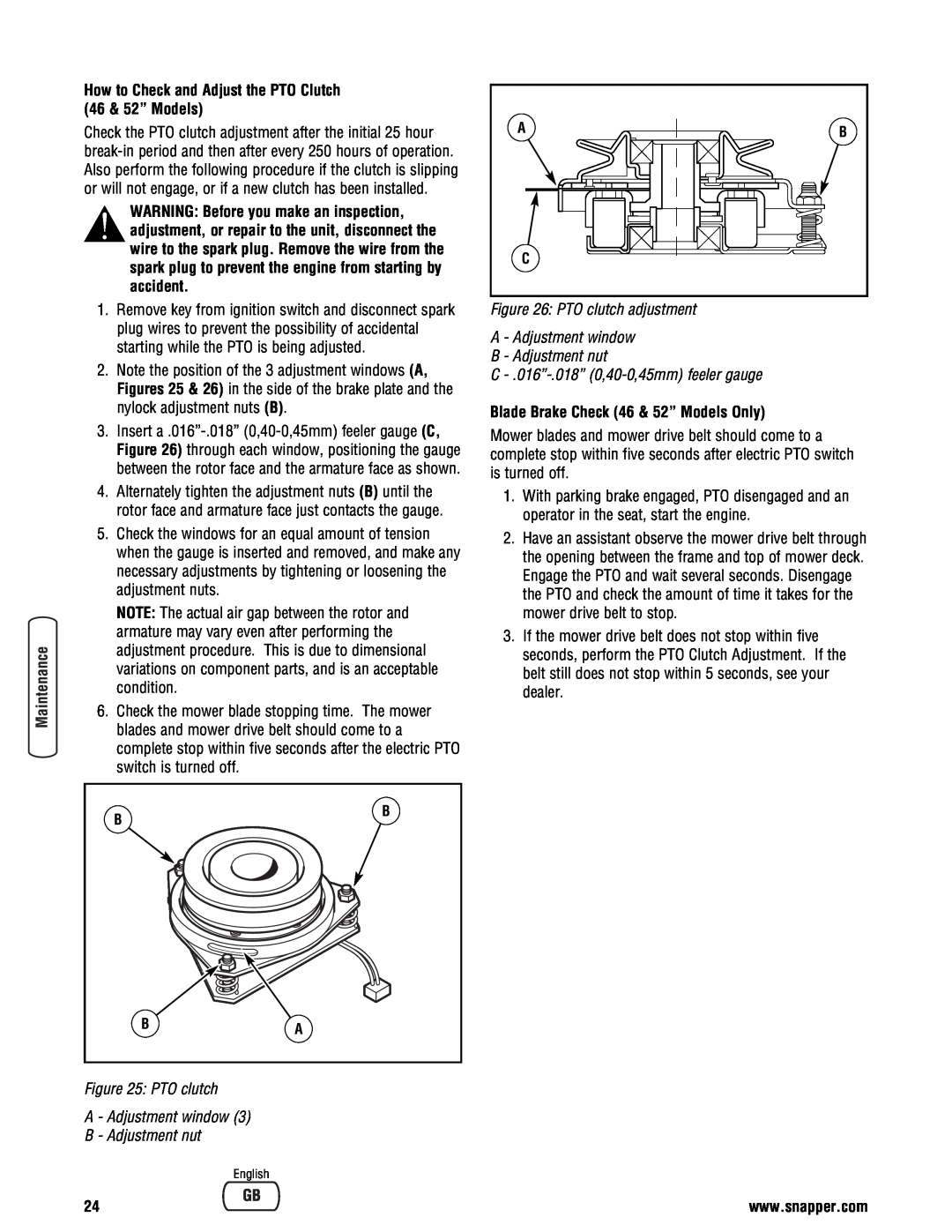
Figure 26: PTO clutch adjustment
A - Adjustment window
B - Adjustment nut
C - .016”-.018” (0,40-0,45mm) feeler gauge
Blade Brake Check (46 & 52” Models Only)
Mower blades and mower drive belt should come to a complete stop within five seconds after electric PTO switch is turned off.
1.With parking brake engaged, PTO disengaged and an operator in the seat, start the engine.
2.Have an assistant observe the mower drive belt through the opening between the frame and top of mower deck. Engage the PTO and wait several seconds. Disengage the PTO and check the amount of time it takes for the mower drive belt to stop.
3.If the mower drive belt does not stop within five seconds, perform the PTO Clutch Adjustment. If the belt still does not stop within 5 seconds, see your dealer.
B | A |
|
Figure 25: PTO clutch
A - Adjustment window (3)
B - Adjustment nut
English
24 | www.snapper.com |