How to Check and Adjust the Motion Drive Belt
If the motion drive belt is loose, the belt will slip when; (1) going up a hill, (2) pulling a heavy load, or (3) the unit will not move forward. Adjust the belt as follows.
WARNING: Before you make an inspection, adjustment, or repair to the unit, disconnect the wire to the spark plug. Remove the wire from the spark plug to prevent the engine from starting by accident.
1.Check the routing of the motion drive belt. Make sure the belt is installed correctly and is inside all the belt guides.
2.Disconnect the clutch link from the idler arm (Figure 27).
3.Align the hole in the brake lever with the hole in the frame. Hold the brake lever in place with a 1/4 inch (6 mm) pin or bolt (Figure 28).
4.Rotate the clutch link until the mounting hole in the clutch link is aligned with the hole in the idler arm as shown in Figure 27.
5.Connect the clutch link to the idler arm (Figure 27).
6.Remove the 1/4 inch (6 mm) pin or bolt (Figure 28).
B | C | D |
|
| |
| A |
|
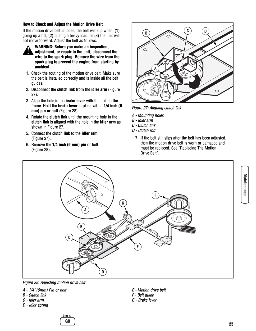
Figure 27: Aligning clutch link
A - Mounting holes
B - Idler arm
C - Clutch link
D - Clutch rod
7.If the belt still slips after the belt has been adjusted, then the motion drive belt is worn or damaged and must be replaced. See “Replacing The Motion Drive Belt”.
F |
G |
A |
B |
C |
E |
D |
Figure 28: Adjusting motion drive belt
A - 1/4" (6mm) Pin or bolt | E - Motion drive belt |
B - Clutch link | F - Belt guide |
C - Idler arm | G - Brake lever |
D - Idler spring |
|
English |
|
25