FM/AM
Compact Disc
Player
Installation/Connections
Installation/Connexions
Instalación/Conexiones
CDX-MP70
Sony Corporation © 2002 Printed in Korea
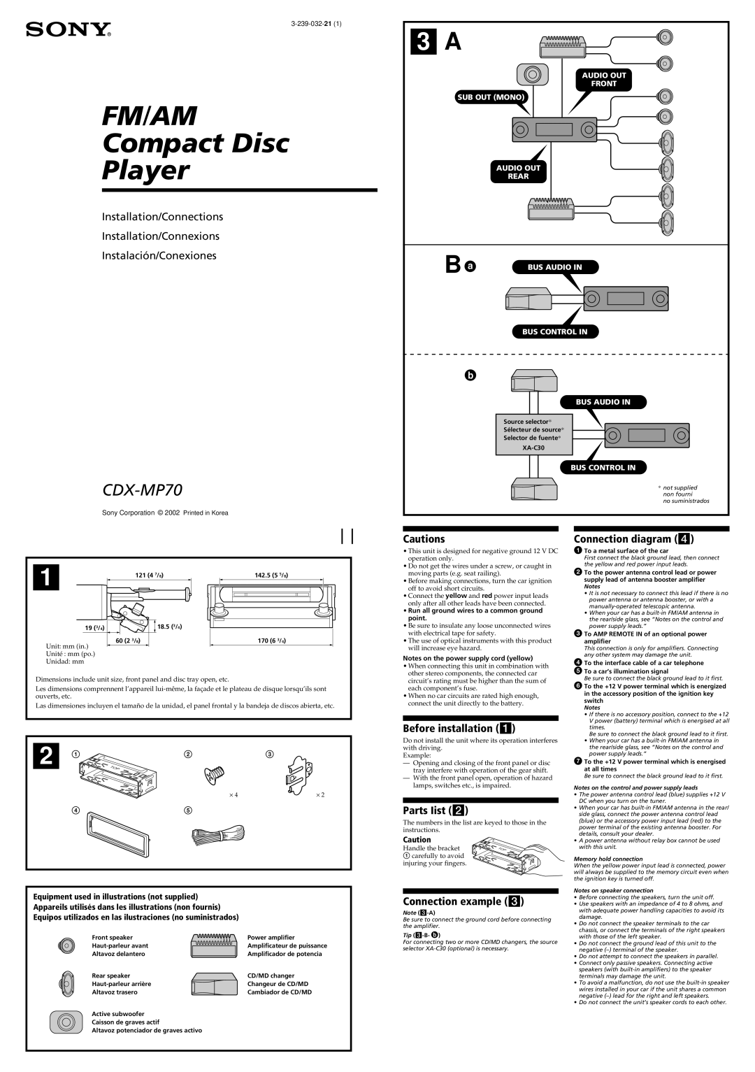
3 A
AUDIO OUT
FRONT
SUB OUT (MONO)
AUDIO OUT
REAR
B | BUS AUDIO IN |
|
BUS CONTROL IN
BUS AUDIO IN
Source selector*
Sélecteur de source*
Selector de fuente*
BUS CONTROL IN
* not supplied
non fourni
no suministrados
1 | 121 (4 | 7/8) | 142.5 (5 5/8) |
| |||
19 (3/4) |
| 18.5 (3/4) |
|
Unit: mm (in.) | 60 (2 3/8) |
| 170 (6 3/4) |
|
|
| |
Unité : mm (po.) |
|
|
|
Unidad: mm |
|
|
|
Dimensions include unit size, front panel and disc tray open, etc.
Les dimensions comprennent l’appareil
Las dimensiones incluyen el tamaño de la unidad, el panel frontal y la bandeja de discos abierta, etc.
2 1 | TOP | 2 | 3 |
⋅ 4 | ⋅ 2 |
45
Equipment used in illustrations (not supplied)
Appareils utilisés dans les illustrations (non fournis)
Equipos utilizados en las ilustraciones (no suministrados)
Front speaker | Power amplifier |
Amplificateur de puissance | |
Altavoz delantero | Amplificador de potencia |
Rear speaker | CD/MD changer |
Changeur de CD/MD | |
Altavoz trasero | Cambiador de CD/MD |
Active subwoofer |
|
Caisson de graves actif |
|
Altavoz potenciador de graves activo |
|
Cautions
•This unit is designed for negative ground 12 V DC operation only.
•Do not get the wires under a screw, or caught in moving parts (e.g. seat railing).
•Before making connections, turn the car ignition off to avoid short circuits.
•Connect the yellow and red power input leads only after all other leads have been connected.
•Run all ground wires to a common ground point.
•Be sure to insulate any loose unconnected wires with electrical tape for safety.
•The use of optical instruments with this product will increase eye hazard.
Notes on the power supply cord (yellow)
•When connecting this unit in combination with other stereo components, the connected car circuit’s rating must be higher than the sum of each component’s fuse.
•When no car circuits are rated high enough, connect the unit directly to the battery.
Before installation (1)
Do not install the unit where its operation interferes with driving.
Example:
—Opening and closing of the front panel or disc tray interfere with operation of the gear shift.
—With the front panel open, operation of hazard lamps, switches etc., is impaired.
Parts Iist (2)
The numbers in the list are keyed to those in the instructions.
Caution
Handle the bracket | TO | P |
1 carefully to avoid |
|
|
injuring your fingers. |
|
|
Connection example (3)
Note
Be sure to connect the ground cord before connecting the amplifier.
Tip (3-B- )
For connecting two or more CD/MD changers, the source selector
Connection diagram (4)
1To a metal surface of the car
First connect the black ground lead, then connect the yellow and red power input leads.
2To the power antenna control lead or power supply lead of antenna booster amplifier Notes
•It is not necessary to connect this lead if there is no power antenna or antenna booster, or with a
•When your car has a
3To AMP REMOTE IN of an optional power amplifier
This connection is only for amplifiers. Connecting any other system may damage the unit.
4To the interface cable of a car telephone
5To a car’s illumination signal
Be sure to connect the black ground lead to it first.
6To the +12 V power terminal which is energized in the accessory position of the ignition key switch
Notes
•If there is no accessory position, connect to the +12 V power (battery) terminal which is energised at all times.
Be sure to connect the black ground lead to it first.
•When your car has a
7To the +12 V power terminal which is energised at all times
Be sure to connect the black ground lead to it first.
Notes on the control and power supply leads
•The power antenna control lead (blue) supplies +12 V DC when you turn on the tuner.
•When your car has
•A power antenna without relay box cannot be used with this unit.
Memory hold connection
When the yellow power input lead is connected, power will always be supplied to the memory circuit even when the ignition key is turned off.
Notes on speaker connection
•Before connecting the speakers, turn the unit off.
•Use speakers with an impedance of 4 to 8 ohms, and with adequate power handling capacities to avoid its damage.
•Do not connect the speaker terminals to the car chassis, or connect the terminals of the right speakers with those of the left speaker.
•Do not connect the ground lead of this unit to the negative
•Do not attempt to connect the speakers in parallel.
•Connect only passive speakers. Connecting active speakers (with
•To avoid a malfunction, do not use the
•Do not connect the unit’s speaker cords to each other.