Contents
GDM-F500/F500T9
Leakage Test
Safety CHECK-OUT
To change the power saving delay time
Power Saving Function
Timing Specification
Table of Contents
Identifying parts and controls
Precautions
Section
General
Connect the power cord
Connect your monitor to your computer
Turn on the monitor and computer
Automatically sizing and centering the picture
Connecting Universal Serial Bus USB compliant peripherals
Selecting the input signal
Selecting the on-screen menu language Lang
Picture Center
Adjusting the brightness and contrast
Adjusting the size of the picture Size
Navigating the menu
Enlarging or reducing the picture
Adjusting the shape of the picture Geom
Adjusting the color of the picture Color
Adjusting the quality of the picture Screen
If thin lines appear on your screen damper wires
Additional settings Option
Resetting the adjustments
Preset and user modes
Symptom Check these items Picture is ghosting
Trouble symptoms and remedies
Self-diagnosis function
If the 1 power indicator is green
Section Disassembly
Cabinet Removal
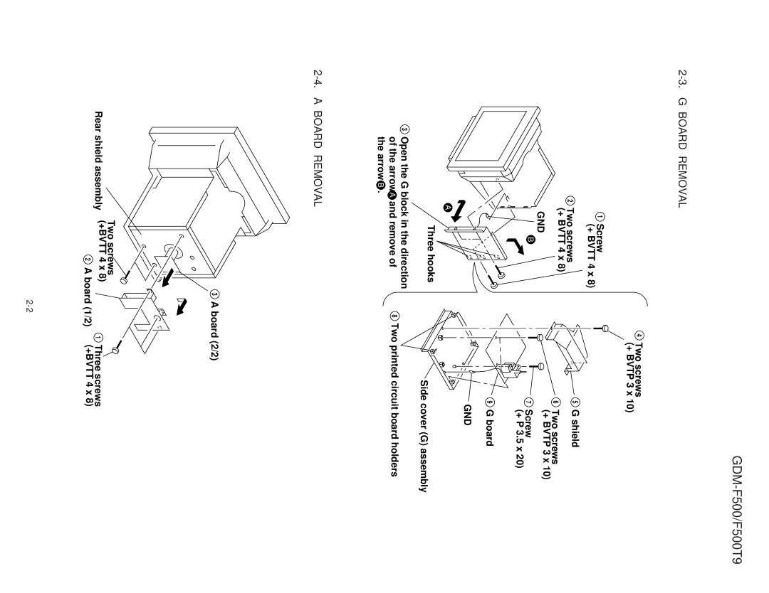
Board Removal
Screw + Bvtt 4 x Two screws + Bvtt 4 x
Service Position
US Board Removal
H1, H2 and J Boards Removal
GND DY
Picture Tube Removal
FBT
Harness Location
+ Voltage Check
Section Safety Related Adjustment
∙ Landing Fine Adjustment
Adjustments
Mode
∙ Convergence Rough Adjustment
Block Diagrams
Section Diagrams
Page
5BNC Video AMP, RGB OUT
Frame Schematic Diagram
Schematic Diagrams and Printed Wiring Boards
Circuit Boards Location
Board Component Side
Focus
1/2 D 2/2 board JL boards l
Schematic diagrams
Power Supply
Schematic diagram Board l
STAT, H.STAT, LCC GEO Magnetic Sensor
Video AMP
Videorgb Outamp
GND3
Schematic diagram Us board l
USB Control
F500 AEPS/N 2,801,281 and later
US Board Conductor Side
Schematic diagram
Semiconductors
FMQ-G5GS D5L60
2SC4686A Lbsony EGP10D
EGP10GPKG23
D2S4MF D2S4MTA1
Exploded Views
Chassis
REF.NO. Part no Description Remark
Picture Tube
Packing Materials
Memo
List
REF.NO. Part NO. Description Remark REF.NO. Part no
REF.NO Description Remark Part NO. Description
Remark REF.NO Description
REF.NO Description
Resistor
REF.NO Part NO. Description Remark
Coil
IC Link
REF.NO Part NO. Description
SOCKET, Picture Tube
Spark GAP
GAP, Spark
Socket
PLUG, Connector 5P
PIN, Connector with PWB
PIN, Connector PC Board 3P
PLUG, Connector 12P
REF.NO Description Remark
Replace only with part number specified
Relay
Spring AA, TR Retainer
Screw +BVTP 3X10 TYPE2 TTB
Metal
2KV
PLUG, Connector 2P
PLUG, Connector 9P
PIN, Connector PC Board 6P
PIN, Connector PC Board 10P
Zener Diode DTZ5.1B
Diode MA111
COIL, Horizontal Linearity
Diode 1SS184
R063 216-025-91 RES,CHIP 100 10W R001
REF.NO Part NO. Description
Switch
TRANSFORMER, Ferrite HDT
TRANSFORMER, Ferrite HST
PIN, Connector PC Board 12P
Metal Thermistor Switch
SWITCH, Stick Cont +/-, BRT + Crystal Thermistor
Diode SLR-325YCT31 Connector Transistor
Switch Connector
SWITCH, Push AC Power
Sensor
Ceramic Chip 0.01 F
US BOARD, Complete OLD
US BOARD, Complete NEW
Ceramic Chip 0.1 F
FB2913 Short C2916 10% 25V FB2914
NEW OLD
OLD Transformer
978-620-12
English

