KL-W7000
Specifications
Safety CHECK-OUT
Table of Contents
Installing the projection monitor
Precautions
Optimum viewing area
Hookup
User modes
Connecting to a Macintosh or compatible computer
Preset and user modes Preset modes
For customers using Windows
Language
Changing the menu
Muting the sound
Watching the picture in wide picture mode
Projecting the picture
To turn off the monitor
Adjusting the position of a computer picture
Recommended picture mode
Adjusting the vertical position of the video picture
Watching the computer picture in wide picture mode
Adjusting the picture size Size
Adjusting the computer picture
Selecting the preset picture viewing mode
Adjusting the position Center
Adjusting the picture in more details
Adjusting
Selecting the audio
Adjusting the sound
Cleaning the air filter
Turning the power off automatically
Replacing a lamp
Troubleshooting
U indicator lights
Identifying the parts
Section Disassembly
Power Block and K Board Removal Filter Removal
Lamp Removal
Extension Cable C Board
Function of commander in Service mode
Adjustment in Service mode
Screen in Service mode
Basic Adjustment in Service Mode
Aout NVM A2 Data
CXA2011Q
WB CXA1315
BIAS3 CXA1315
CXD2052 Digital Chroma Decoder
3C 3-Dimensional Com μ PD6487
1C 3-Dimensional Com μ PD6486
CXA1839
MID2 CXD2072Q RGB
MID2 CXD2072Q Video
Display Name
AP TA8776N
Aion AI Auto
OP Others
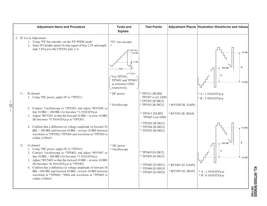
Adjustment Places Illustration Waveforms and Values
Use TP5201
GND
Stop the voltage application to *TP5411 RV5403 RL. Gain
Glbs
AV Memory
Service mode, adjust *CXA1839 No.6 SPC2 so that
Preparation
WB Bcoi
Lens Focus Adjustment
Diagrams
KL-W7000/W9000
KL-W7000/W9000
Memo
HB Board
Board
∙ K Board Voltage List
TA Board
Board Conductor Side
∙ a Board Semiconductor Location
∙ a 1/3 Board Waveforms
Schematic Diagram of a 1/3 Board
A1/3 Board
IC1602 S-80743AL-A7
∙ a 2/3 Board Voltage List
Schematic Diagram of a 2/3 Board
A2/3 Board IC2001 µPC659AGS
∙ a 2/3 Board Waveforms
∙ a 3/3 Board Waveforms
Schematic Diagram of a 3/3 Board
∙ a 3/3 Board Voltage List
∙ BB Board Waveforms
Schematic Diagram of BB Board
∙ BB Board Voltage List
BB Board
BB Board Component Side BB Board Conductor Side
Terminal name of semiconductors
Board Conductor Side Board Component Side
Silk screen printed circuit
∙ U Board Waveforms
Schematic Diagram of U Board
∙ U Board Voltage List
∙ C 1/2 Board Waveforms
Schematic Diagram of C 1/2 Board
∙ C 1/2 Board Voltage List
∙ C 2/2 Board Waveforms
Schematic Diagram of C 2/2 Board Board Conductor Side
∙ C 2/2 Board
Voltage List
∙ G Board Voltage List
Schematic Diagram of G and GA Boards
GA Board
Semiconductors
100
Screw M4 EXT Tooth Washer
Power Block
BRACKET, U
HOLDER, Printed Circurt Board
Strike
BUTTON, Power
Panel L ASSY, Front
Latch
Plate L, Duffusion
Frame ASSY, Screen
HOLDER, Printed Circuit Board
SCREEN, Contrast
SCREW, TAPPING, Hexagon Head
CLAMP, Cord
BB BOARD, Complete
Pedestal
HA BOARD, Complete
TA BOARD, Complete
ÁA-1501-247-A Lamp Block Assy
Holder R, Mirror
Cover 50, Service
Holder 50, Screen
Holder R ASSY, Mirror
Ceramic Chip 0.1MF
ABB BOARD, Complete
Case Bottom LID, Shield
Capacitor
IC TC7SHU04FU
Connector
IC TC7SET04FUTE85R
IC TC7SET08FU-TE85L
Short
Metal Chip
Elect 1MF
Ceramic Chip 0.01MF
Ceramic Chip 100PF
Ceramic Chip 220PF
111
PLUG, Connector 3P
PLUG, Connector 4P
PLUG, Connector 10P
CONNECTOR, Board to Board 11P
0UH
Diode
Chip Conductor
Ferrite Bead Coil
Inductor 22UH
Inductor 18UH
Transistor 2SD601A-Q
Inductor 10UH
115
116
117
CONNECTOR, Board to Board 10P
PLUG, Connector 6P
PLUG, Connector 10P Capacitor
PIN, Connector PC Board 3P
Diode D10SC4M
COIL, Choke
Diode D10SBS4F
Diode D10SC6M
AGA BOARD, Complete
Wirewound Capacitor
Carbon Connector
CONNECTOR, Bpard to Board 10P
121
FILTER, EMI Diode
CONNECTOR, FFC ZIF 20P
FILTER, EMI
FILTER, Chip EMI
123
Gain
Variable Resistor
Vcom
Diode TLR124
Jack Connector
AHA BOARD, Complete
Diode TLG124A
SWITCH, Tactil →
Switch
SWITCH, Tactil Input Select
SWITCH, Tactil Enter
Zener Diode RD10SB Filter
Zener Diode RD10SB
Zener Diode DTZ5.1B
Diode MA111
128
AK BOARD, Complete
ATA BOARD, Complete IC Link
Connector Transistor
SWITCH, Micro Lamp Cover
SWITCH, Micro Filter Cover
Miscellaneous INLET, AC 3PWITH Noise Filte
Remote Commander
Display Company
Quality Assurance Department Service Promotion Section