Sub Colour Adjustment
1.Receive a PAL colour bar signal.
2.Connect an oscilloscope to Pin 5 of CN003 [A Board].
3.Enter into the ‘Service’ service menu.
4.Adjust the ‘Sub Colour’ data so that the Cyan, Magenta and Blue colour bars are of equal levels as indicated below.
Same Level
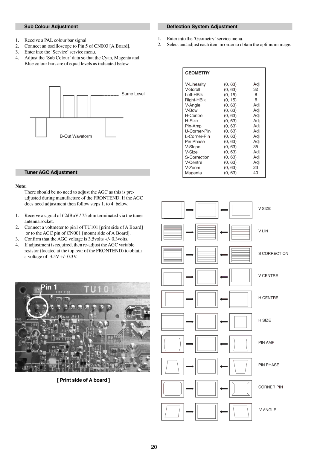
Tuner AGC Adjustment
Note:
There should be no need to adjust the AGC as this is pre- adjusted during manufacture of the FRONTEND. If the AGC does need adjustment then follow steps 1. to 4. below.
1.Receive a signal of 62dBuV / 75 ohm terminated via the tuner antenna socket.
2.Connect a voltmeter to pin1 of TU101 [print side of A Board] or to the AGC pin of CN001 [mount side of A Board].
3.Confirm that the AGC voltage is 3.5volts +/- 0.3volts.
4.If adjustment is required, then
Deflection System Adjustment
1.Enter into the ‘Geometry’ service menu.
2.Select and adjust each item in order to obtain the optimum image.
GEOMETRY |
|
|
(0, 63) | Adj | |
(0, 63) | 32 | |
(0, 15) | 8 | |
(0, 15) | 6 | |
(0, 63) | Adj | |
(0, 63) | Adj | |
(0, 63) | Adj | |
(0, 63) | Adj | |
(0, 63) | Adj | |
(0, 63) | Adj | |
(0, 63) | Adj | |
Pin Phase | (0, 63) | Adj |
(0, 63) | 35 | |
(0, 63) | Adj | |
(0, 63) | Adj | |
(0, 63) | Adj | |
(0, 63) | 23 | |
Magenta | (0, 63) | 40 |
|
|
|
V SIZE
V LIN
S CORRECTION
V CENTRE
H CENTRE
H SIZE
PIN AMP
PIN PHASE
[ Print side of A board ]
CORNER PIN
V ANGLE
20