Connecting and Installing the TV (continued)
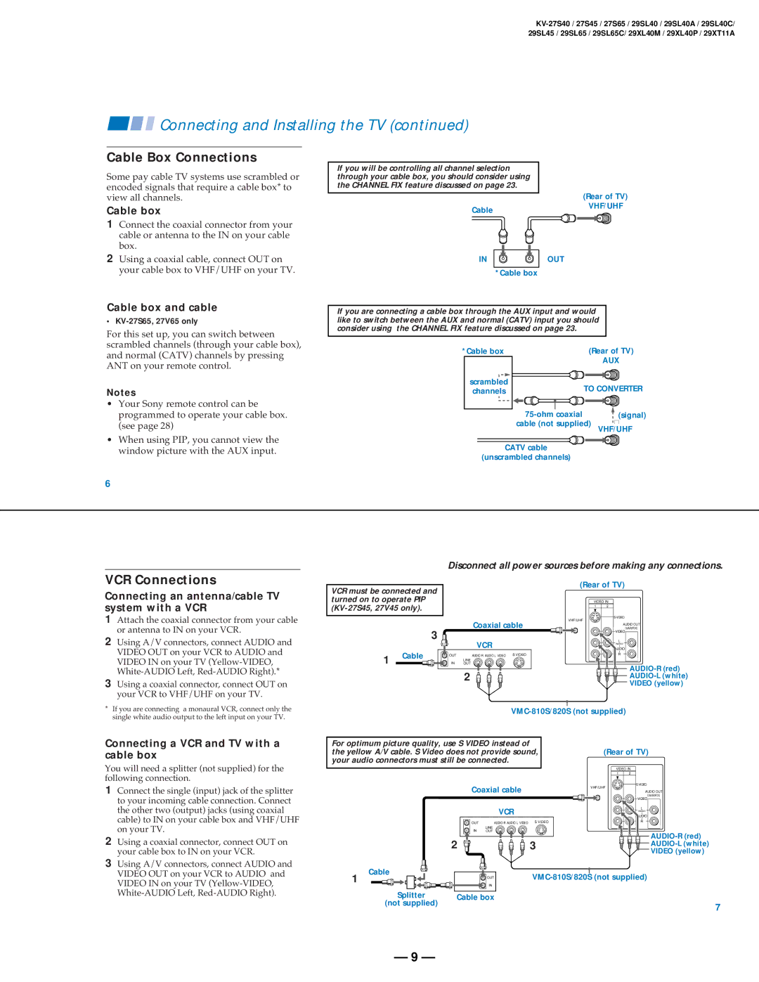
Cable Box Connections
Some pay cable TV systems use scrambled or encoded signals that require a cable box* to view all channels.
Cable box
1Connect the coaxial connector from your cable or antenna to the IN on your cable box.
2Using a coaxial cable, connect OUT on your cable box to VHF/UHF on your TV.
If you will be controlling all channel selection through your cable box, you should consider using the CHANNEL FIX feature discussed on page 23.
Cable
IN
*Cable box
OUT
(Rear of TV)
VHF/UHF
Cable box and cable
•
For this set up, you can switch between scrambled channels (through your cable box), and normal (CATV) channels by pressing ANT on your remote control.
Notes
•Your Sony remote control can be programmed to operate your cable box. (see page 28)
•When using PIP, you cannot view the window picture with the AUX input.
If you are connecting a cable box through the AUX input and would like to switch between the AUX and normal (CATV) input you should consider using the CHANNEL FIX feature discussed on page 23.
*Cable box | (Rear of TV) | |
| AUX | |
scrambled | TO CONVERTER | |
channels | ||
| ||
(signal) |
cable (not supplied) VHF/UHF
CATV cable
(unscrambled channels)
6
Disconnect all power sources before making any connections.
VCR Connections
Connecting an antenna/cable TV system with a VCR
1Attach the coaxial connector from your cable or antenna to IN on your VCR.
2Using A/V connectors, connect AUDIO and VIDEO OUT on your VCR to AUDIO and VIDEO IN on your TV
3Using a coaxial connector, connect OUT on your VCR to VHF/UHF on your TV.
VCR must be connected and turned on to operate PIP
Coaxial cable
3 ![]()
![]()
![]()
VCR
1 | Cable | OUT | AUDIO R AUDIO L VIDEO S VIDEO |
| |||
| IN | LINE | |
| OUT |
2 ![]()
![]()
![]()
(Rear of TV)
VIDEO IN
1 2
S VIDEO
VHF/UHF
AUDIO OUT
(VAR/FIX)
VIDEO
L
(MONO)
AUDIO
R


AUDIO-R (red)


AUDIO-L (white)

 VIDEO (yellow)
*If you are connecting a monaural VCR, connect only the single white audio output to the left input on your TV.
Connecting a VCR and TV with a cable box
You will need a splitter (not supplied) for the following connection.
1Connect the single (input) jack of the splitter to your incoming cable connection. Connect the other two (output) jacks (using coaxial cable) to IN on your cable box and VHF/UHF on your TV.
2Using a coaxial connector, connect OUT on your cable box to IN on your VCR.
3Using A/V connectors, connect AUDIO and VIDEO OUT on your VCR to AUDIO and VIDEO IN on your TV
|
|
|
| |||
For optimum picture quality, use S VIDEO instead of |
|
|
| |||
the yellow A/V cable. S Video does not provide sound, | (Rear of TV) | |||||
your audio connectors must still be connected. |
|
|
| |||
|
|
|
|
| VIDEO IN | |
|
|
|
|
| 1 | 2 |
|
| Coaxial cable |
| VHF/UHF | S VIDEO | |
|
|
|
| |||
|
|
|
| AUDIO OUT | ||
|
|
|
|
|
| (VAR/FIX) |
|
|
|
|
|
| VIDEO |
|
|
| VCR |
|
| L |
|
|
|
|
| (MONO) | |
|
|
|
|
|
| AUDIO |
|
| OUT | AUDIO R AUDIO L VIDEO S VIDEO |
| R | |
|
| IN | LINE |
|
|
|
|
| OUT |
|
| ||
|
| 2 |
| 3 |
| |
|
|
|
| |||
|
|
|
|
|
| VIDEO (yellow) |
1 | Cable |
| OUT | |||
|
| |||||
|
|
| IN |
|
|
|
| Splitter | Cable box |
|
|
| |
| (not supplied) |
|
|
|
| 7 |
|
|
|
|
|
| |
— 9 —