SECTION 4
SAFETY RELATED ADJUSTMENTS
ABOARD
![]() R584 CONFIRMATION METHOD (HV
R584 CONFIRMATION METHOD (HV
The following adjustments should always be performed when replacing the following components which are marked with ] on the schematic diagram:
DY, C511,C572, C573, C574, C575, D573, D574, R582, R583 R585, R586, R578, R579, T504, IC301, IC521, IC603, C507, C508, C509, C515, C520, L591,L501
(1)Preparation before Confirmation
Using Variac, apply AC input voltage: 120+2VAC (or 220 + 2 VAC for
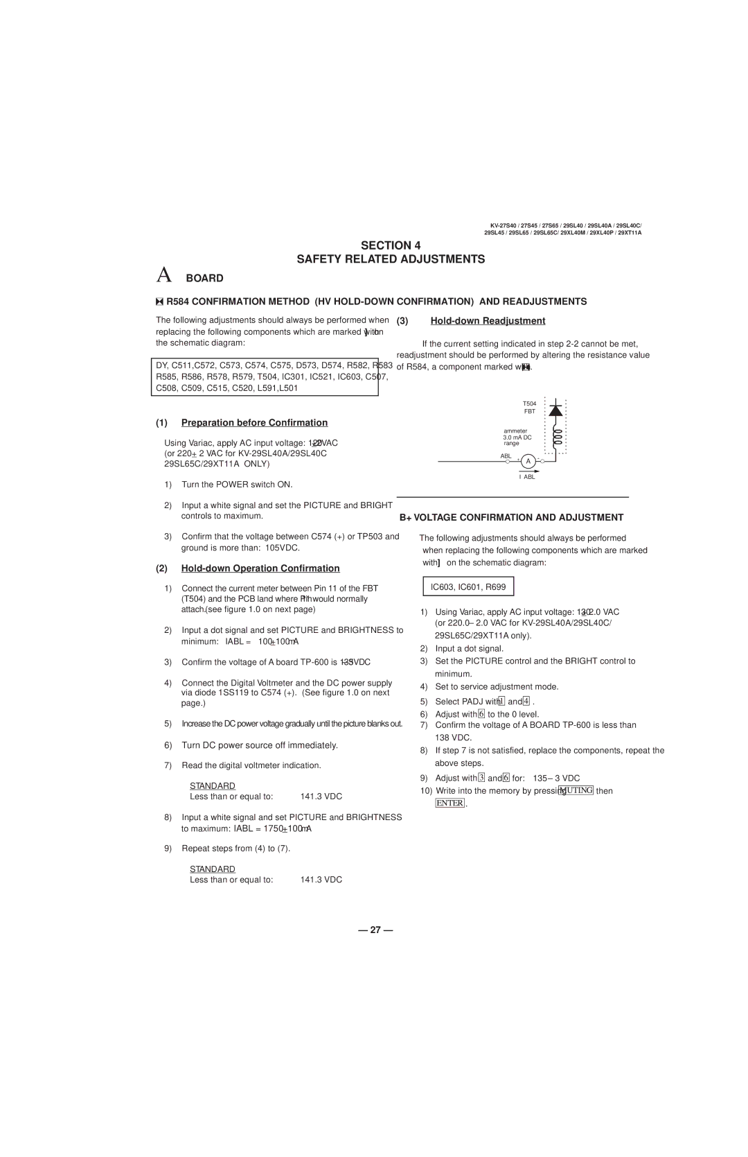
(3)Hold-down Readjustment
If the current setting indicated in step ![]() .
.
T504
FBT
ammeter
3.0 mA DC range
ABL + A -
I ABL
1)Turn the POWER switch ON.
2)Input a white signal and set the PICTURE and BRIGHT controls to maximum.
3)Confirm that the voltage between C574 (+) or TP503 and ground is more than: 105VDC.
(2)Hold-down Operation Confirmation
1)Connect the current meter between Pin 11 of the FBT
(T504) and the PCB land where Pin 11 would normally attach. (see figure 1.0 on next page)
2)Input a dot signal and set PICTURE and BRIGHTNESS to minimum: IABL = 100+100μA
3)Confirm the voltage of A board
4)Connect the Digital Voltmeter and the DC power supply via diode 1SS119 to C574 (+). (See figure 1.0 on next page.)
5)Increase the DC power voltage gradually until the picture blanks out.
6)Turn DC power source off immediately.
7)Read the digital voltmeter indication.
STANDARD |
|
Less than or equal to: | 141.3 VDC |
8)Input a white signal and set PICTURE and BRIGHTNESS to maximum: IABL = 1750+100μA
9)Repeat steps from (4) to (7).
STANDARD |
|
Less than or equal to: | 141.3 VDC |
B+ VOLTAGE CONFIRMATION AND ADJUSTMENT
The following adjustments should always be performed when replacing the following components which are marked with ] on the schematic diagram:
IC603, IC601, R699
1)Using Variac, apply AC input voltage: 130 + 2.0 VAC (or 220.0 ± 2.0 VAC for
29SL65C/29XT11A only).
2)Input a dot signal.
3)Set the PICTURE control and the BRIGHT control to minimum.
4)Set to service adjustment mode.
5)Select PADJ with ![]()
![]()
![]() and
and ![]()
![]()
![]() .
.
6)Adjust with ![]()
![]()
![]() to the 0 level.
to the 0 level.
7)Confirm the voltage of A BOARD
8)If step 7 is not satisfied, replace the components, repeat the above steps.
9)Adjust with ![]()
![]()
![]() and
and ![]()
![]()
![]() for: 135 ± 3 VDC
for: 135 ± 3 VDC
10)Write into the memory by pressing ![]()
![]()
![]() then
then
![]()
![]()
![]() .
.
— 27 —