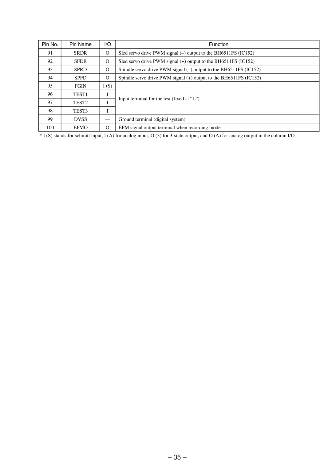
Pin No. | Pin Name | I/O | Function | |
|
|
|
| |
91 | SRDR | O | Sled servo drive PWM signal | |
|
|
|
| |
92 | SFDR | O | Sled servo drive PWM signal (+) output to the BH6511FS (IC152) | |
|
|
|
| |
93 | SPRD | O | Spindle servo drive PWM signal | |
|
|
|
| |
94 | SPFD | O | Spindle servo drive PWM signal (+) output to the BH6511FS (IC152) | |
|
|
|
| |
95 | FGIN | I (S) |
| |
|
|
|
| |
96 | TEST1 | I | Input terminal for the test (fixed at “L”) | |
|
|
| ||
97 | TEST2 | I | ||
| ||||
|
|
|
| |
98 | TEST3 | I |
| |
|
|
|
| |
99 | DVSS | — | Ground terminal (digital system) | |
|
|
|
| |
100 | EFMO | O | EFM signal output terminal when recording mode | |
|
|
|
|
* I (S) stands for schmitt input, I (A) for analog input, O (3) for
– 35 –