7.Then, rotate the [ÊÊÊÊÊÊÊÊAMSÊÊÊÊÊÊÊÊ]- ± knob and display “LDPWR CHECK” (C02).
8.Press the [YES] button once and display “LD 0.9 mW $ ![]()
![]() ”. Check that the reading of the laser power meter become 0.85 to 0.91 mW.
”. Check that the reading of the laser power meter become 0.85 to 0.91 mW.
9.Press the [YES] button once more and display “LD 7.0 mW $
![]()
![]() ”. Check that the reading the laser power meter and digital volt meter satisfy the specified value.
”. Check that the reading the laser power meter and digital volt meter satisfy the specified value.
Note down the digital voltmeter reading value.
Specification:
Laser power meter reading: 7.0 ± 0.2 mW
Digital voltmeter reading : Optical
(Optical
KMS260A
27X40 B0567
lOP=56.7 mA in this case
lOP (mA) = Digital voltmeter reading (mV)/1 (Ω)
10.Press the [MENU/NO] button and display “LDPWR CHECK” and stop the laser emission.
(The [MENU/NO] button is effective at all times to stop the laser emission.)
11.Rotate the [ÊÊÊÊÊÊÊÊAMSÊÊÊÊÊÊÊÊ]- ± knob to display “Iop.Write”(C28).
12.Press the [YES] button. When the display becomes Ref=@@@.@ (@ is an arbitrary number), press the [YES] button to display “Measu=@@@.@” (@ is an arbitrary num- ber).
13.The numbers which can be changed will blink. Input the Iop value noted down at step 9.
To select the number : Rotate the [ÊÊÊÊÊÊÊÊAMSÊÊÊÊÊÊÊÊ]- ± knob.
To select the digit : Press the [ÊÊÊÊÊÊÊÊAMSÊÊÊÊÊÊÊÊ]- ± knob.
14.When the [YES] button is pressed, “Complete!” will be dis- played momentarily. The value will be recorded in the non- volatile memory and the display will become “Iop Write”.
Note 1: After step 4, each time the [YES] button is pressed, the display
will be switched between “LD 0.7 mW $ ![]()
![]()
![]()
![]() ”, “LD 6.2 mW $
”, “LD 6.2 mW $
![]()
![]() ”, and “LD Wp
”, and “LD Wp ![]()
![]()
![]()
![]() $
$ ![]()
![]()
![]()
![]() ”. Nothing needs to be performed here.
”. Nothing needs to be performed here.
11. TRAVERSE ADJUSTMENT
Note 1: Data will be erased during MO reading if a recorded disc is used in this adjustment.
Note 2: If the traverse waveform is not clear, connect the oscilloscope as shown in the following figure so that it can be seen more clearly.
BD board
![]() 330 k Ω
330 k Ω
CN110 pin 3 (TE)
CN110 pin 1 (VC) ![]() 10 pF
10 pF
Connection :
oscilloscope (DC range)
BD board |
|
| ||
CN110 pin 3 | (TE) | + | V: 0.1 V/div | |
CN110 pin 1 | (VC) | |||
– | H: 10 ms/div | |||
|
|
| ||
Adjusting Procedure :
1.Connect an oscilloscope to CN110 pin 3 (TE) and CN110 pin 1 (VC) of the BD board.
2.Load a disc (any available on the market). (Refer to Note 1.)
3.Press the [ÊÊÊÊÊÊ]) button and move the optical
4.Rotate the [ÊÊÊÊÊÊÊÊAMSÊÊÊÊÊÊÊÊ]- ± knob and display “EF MO ADJUS” (C10).
5.Press the [YES] button and display “EFB = ![]()
![]()
6.Rotate the [ÊÊÊÊÊÊÊÊAMSÊÊÊÊÊÊÊÊ]- ± knob so that the waveform of the oscilloscope becomes the specified value.
(When the [ÊÊÊÊÊÊÊÊAMSÊÊÊÊÊÊÊÊ]- ± knob is rotated, the ![]()
![]() of “EFB=
of “EFB=
![]()
![]() ” changes and the waveform changes.) In this adjustment, waveform varies at intervals of approx. 2%. Adjust the wave- form so that the specified value is satisfied as much as pos- sible.
” changes and the waveform changes.) In this adjustment, waveform varies at intervals of approx. 2%. Adjust the wave- form so that the specified value is satisfied as much as pos- sible.
(Read power traverse adjustment)
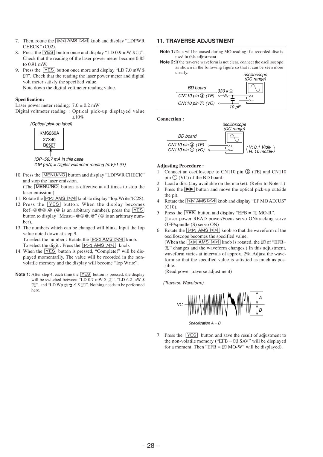
(Traverse Waveform)
A
VC
B
Specification A = B
7.Press the [YES] button and save the result of adjustment to
the ![]()
![]() SAV” will be displayed
SAV” will be displayed
for a moment. Then “EFB = ![]()
![]()
– 28 –