MZ-R900
7)Select the manual mode of the test mode, and set item number 871 (see page 13).
Remote commander LCD display
871 V5num **
**:Adjusted value
8)Adjust with the [VOL+] key (adjusted value up) or
9)Press the X key to write the adjusted value.
10)Select the manual mode of the test mode, and set item number 872 (see page 13).
Remote commander LCD display
872 V5dat **
**:Adjusted value
11)Adjust with the [VOL+] key (adjusted value up) or
12)Press the X key to write the adjusted value.
Power Supply Manual Adjustment
• Adjustment sequence
Adjustment must be done with the following steps.
1.Vc PWM Duty (L) adjustment (item number: 762) r
2.Vc PWM Duty (H) adjustment (item number: 763) r
3.Vl PWM Duty adjustment (item number: 764)
• Setting method of power supply manual adjustment
1.Make sure that the power supply voltage is 3V.
2.Set the test mode (see page 12).
3.Press the . or
Remote commander LCD display
000 Assy00
4.Press the [JOG LEVER $L% r] (down) key, or [PLAYMODE] key on the remote commander.
(Pressing the [JOG LEVER $L% r] (down) key, or [PLAYMODE] key on the remote commander causes the item number to be switched to 762.)
•Adjustment method of Vc PWM Duty (L) (item number: 762)
Remote commander LCD display
762 Vc1PWM **
**: Adjusted value
1.Connect a digital voltmeter to the AP914 (VC) on the MAIN board, and adjust [VOL +] key (voltage up) or [VOL
digital voltmeter
MAIN board
AP914 (VC)
AP912 (GND) ![]()
2.Press the X key to write the adjusted value.
(The item number changes to 763 when X key is pressed)
Adjustment and Connection Location: MAIN board (see page 19)
•Adjustment method of Vc PWM Duty (H) (item number: 763)
Remote commander LCD display
763 VchPWM **
**: Adjusted value
1.Connect a digital voltmeter to the AP914 (VC) on the MAIN
board, and adjust [VOL +] key (voltage up) or [VOL
digital voltmeter
MAIN board
AP914 (VC)
AP912 (GND) ![]()
2.Press the X key to write the adjusted value.
(The item number changes to 764 when X key is pressed)
Adjustment and Connection Location: MAIN board (see page 19)
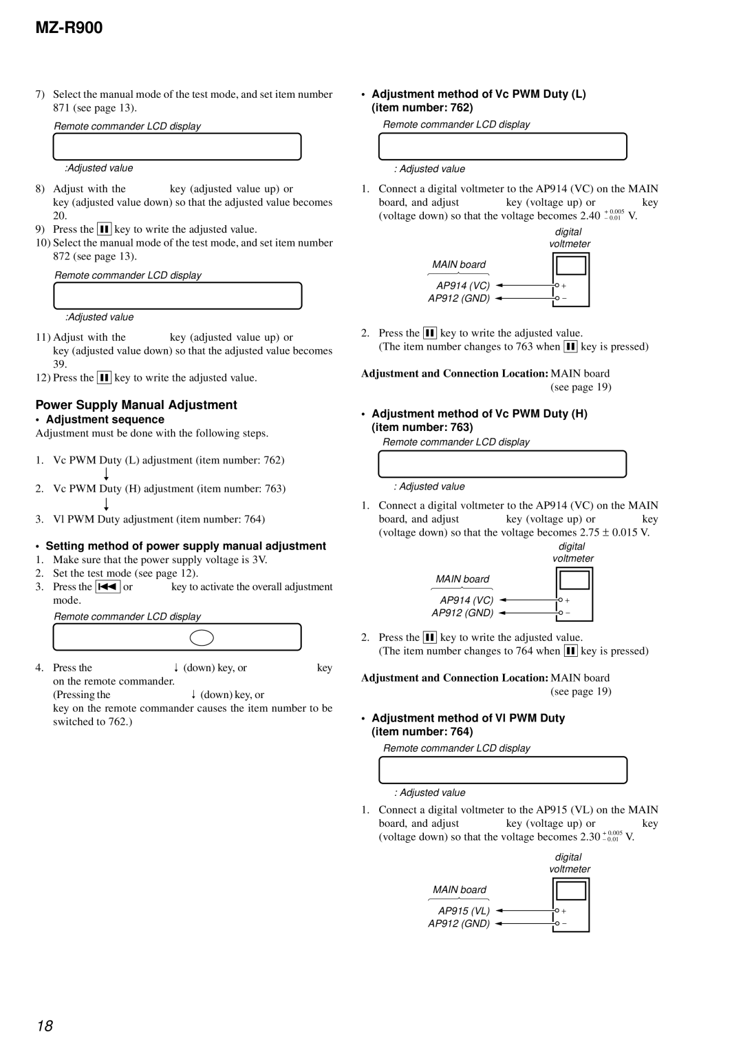
•Adjustment method of Vl PWM Duty (item number: 764)
Remote commander LCD display
764 Vl PWM **
**: Adjusted value
1.Connect a digital voltmeter to the AP915 (VL) on the MAIN board, and adjust [VOL +] key (voltage up) or [VOL
digital voltmeter
MAIN board
AP915 (VL)
AP912 (GND) ![]()
18